Control panel cooling device for machine tool

a technology of cooling device and control panel, which is applied in the direction of manufacturing tools, lighting and heating apparatus, and electric apparatus casings/cabinets/drawers, etc., can solve the problems of increasing the number of components of the cooling device, increasing the failure rate of electric components in the path of air blowing from the cooling device, and increasing the temperature inside the control panel. , to achieve the effect of low parts coun

Inactive Publication Date: 2015-12-17
FANUC LTD
View PDF11 Cites 9 Cited by
  • Summary
  • Abstract
  • Description
  • Claims
  • Application Information

AI Technical Summary

Benefits of technology

[0014]According to the present invention configured as described above, there can be provided a time-saving cooling devi

Problems solved by technology

Depending on the states of the machine tool and its surroundings, the temperature inside the control panel may sometimes increase to damage the components thermally in the control panel.
The installation environment of the machine tool involves a large number of cutting fluid mists.
Although closed control panels are frequently used to protect electric components from the cutting fluid mist atmosphere, they may sometimes allow

Method used


Image

  • Control panel cooling device for machine tool
  • Control panel cooling device for machine tool
  • Control panel cooling device for machine tool

Examples


Embodiment Construction

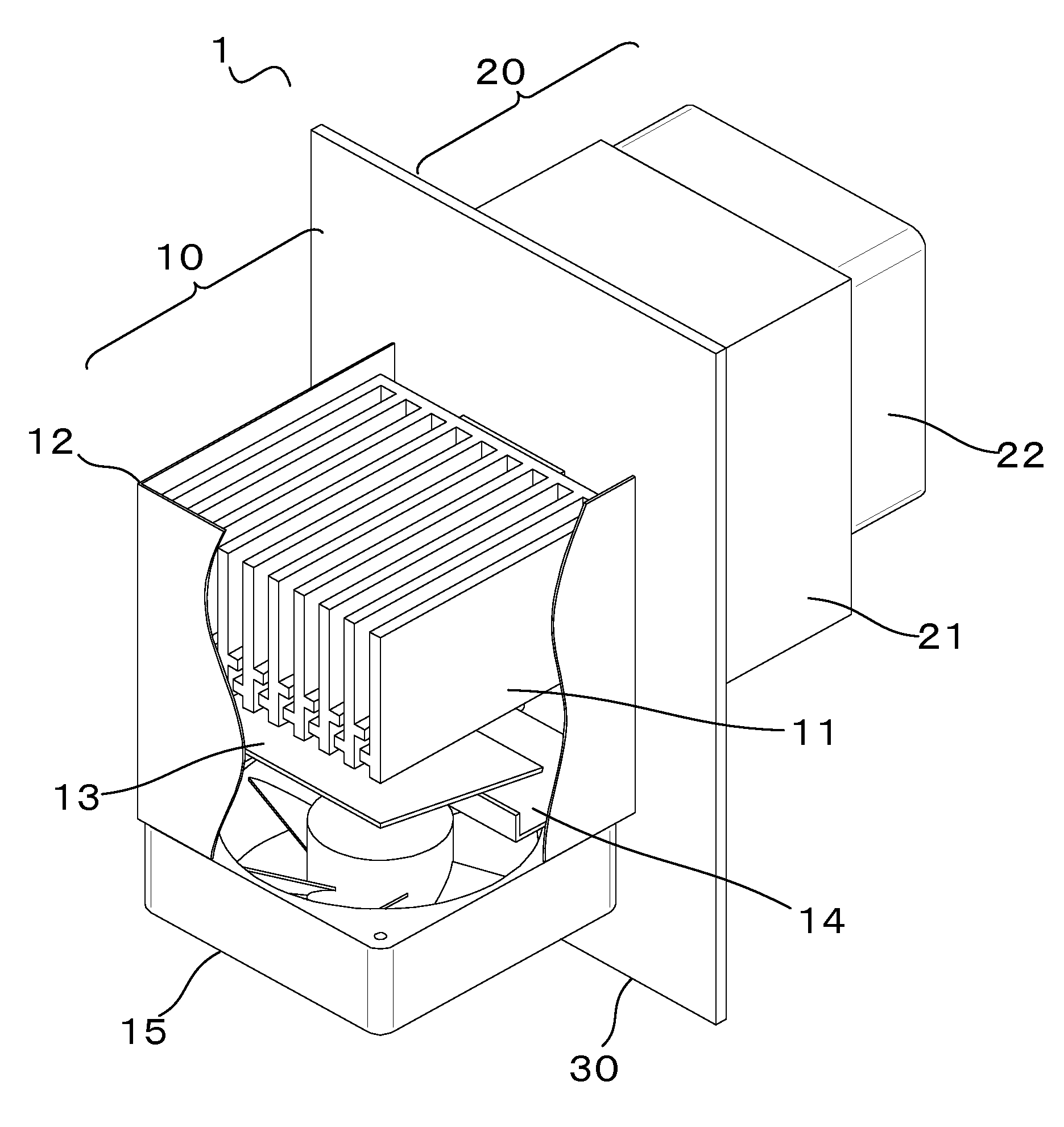
[0021]FIG. 1 is a general view showing a cooling device 1 according to one embodiment of the present invention. The cooling device 1 comprises a cooling unit 10 having a cutting fluid mist collection function and a cooling function and a heat exhaust unit 20 having a heat exhaust function. As shown in FIG. 1, the cooling unit 10 and the heat exhaust unit 20 are mounted on a bracket 30, which is used for attachment to a control panel housing of a machine tool, inside and outside the housing, respectively. The heat exhaust unit 20 will be described in detail later.

[0022]The cooling unit 10 comprises a heat sink 11, cover 12, a droplet guide 13, a tray 14, and a blowing unit 15. As shown in FIG. 1, the heat sink 11, the droplet guide 13, and the tray 14 are mounted so as to be accommodated in the cover 12. Further, the cover 12 is open at its upper end and the blowing unit 15 is attached to its lower end.

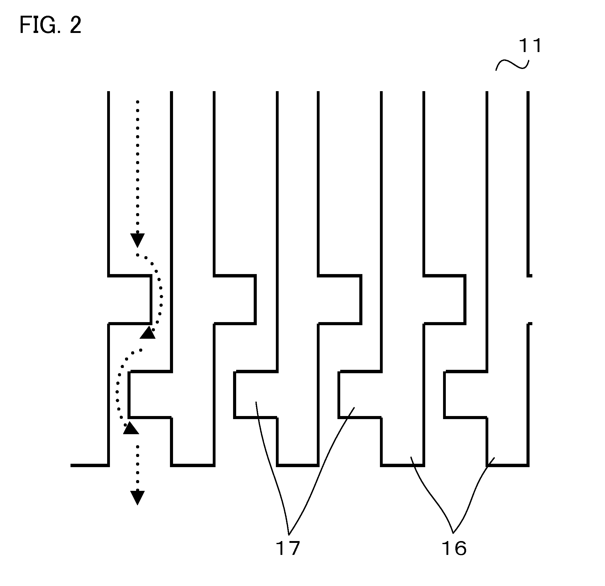
[0023]The heat sink 11 has a function of cooling an ambient atmosphere introduced....


PUM


Abstract

A cooling device with a first heat sink is provided with a blowing unit configured to introduce an ambient atmosphere into the cooling device. The first heat sink is provided with a plurality of fin portions, configured to perform heat exchange when contacted by the ambient atmosphere introduced by the blowing unit, and a mist collection unit horizontally projecting from the fin portions and configured to collect mists in the ambient atmosphere.

Description

BACKGROUND OF THE INVENTION[0001]1. Field of the Invention[0002]The present invention relates to a cooling device, and more particularly, to a cooling device installed in a control panel of a machine tool.[0003]2. Description of the Related Art[0004]A large number of components with a heating portion are installed in a control panel of a machine tool. Depending on the states of the machine tool and its surroundings, the temperature inside the control panel may sometimes increase to damage the components thermally in the control panel. To suppress thermal damage, a method is generally known in which a cooling device, such as a cooling fan or heat exchanger, is installed in the control panel, thereby keeping the temperature low inside the control panel.[0005]The installation environment of the machine tool involves a large number of cutting fluid mists. Although closed control panels are frequently used to protect electric components from the cutting fluid mist atmosphere, they may so...

Claims


Application Information

Patent Timeline
IPC IPC(8): F28F3/02
CPCF28F3/02B23Q11/126F28F17/005H05K7/202H05K5/0212H05K5/0213
Inventor SEKIKAWA, YUUTA
Owner FANUC LTD
Why Eureka
Try Eureka