Radio frequency coupling structure

a frequency coupling and frequency technology, applied in waveguides, instruments, and reradiation, etc., can solve the problem that rf signals may not be transmittable with sufficient strength

Active Publication Date: 2015-12-17
NXP USA INC
View PDF16 Cites 38 Cited by
  • Summary
  • Abstract
  • Description
  • Claims
  • Application Information

AI Technical Summary

Problems solved by technology

The RF signal may be attenuated during the transfer from the integrated circuit package to the external radiating structure in a way such that the RF signal may not be transmittable with sufficient strength.
However, the radio frequency coupling between the first antenna and the second antenna via the conductive layer and the waveguide cannot be controlled such that at the same time low radiation losses and good reproducibility of the radio frequency coupling at affordable costs are achieved.

Method used


Image

  • Radio frequency coupling structure
  • Radio frequency coupling structure
  • Radio frequency coupling structure

Examples


Embodiment Construction

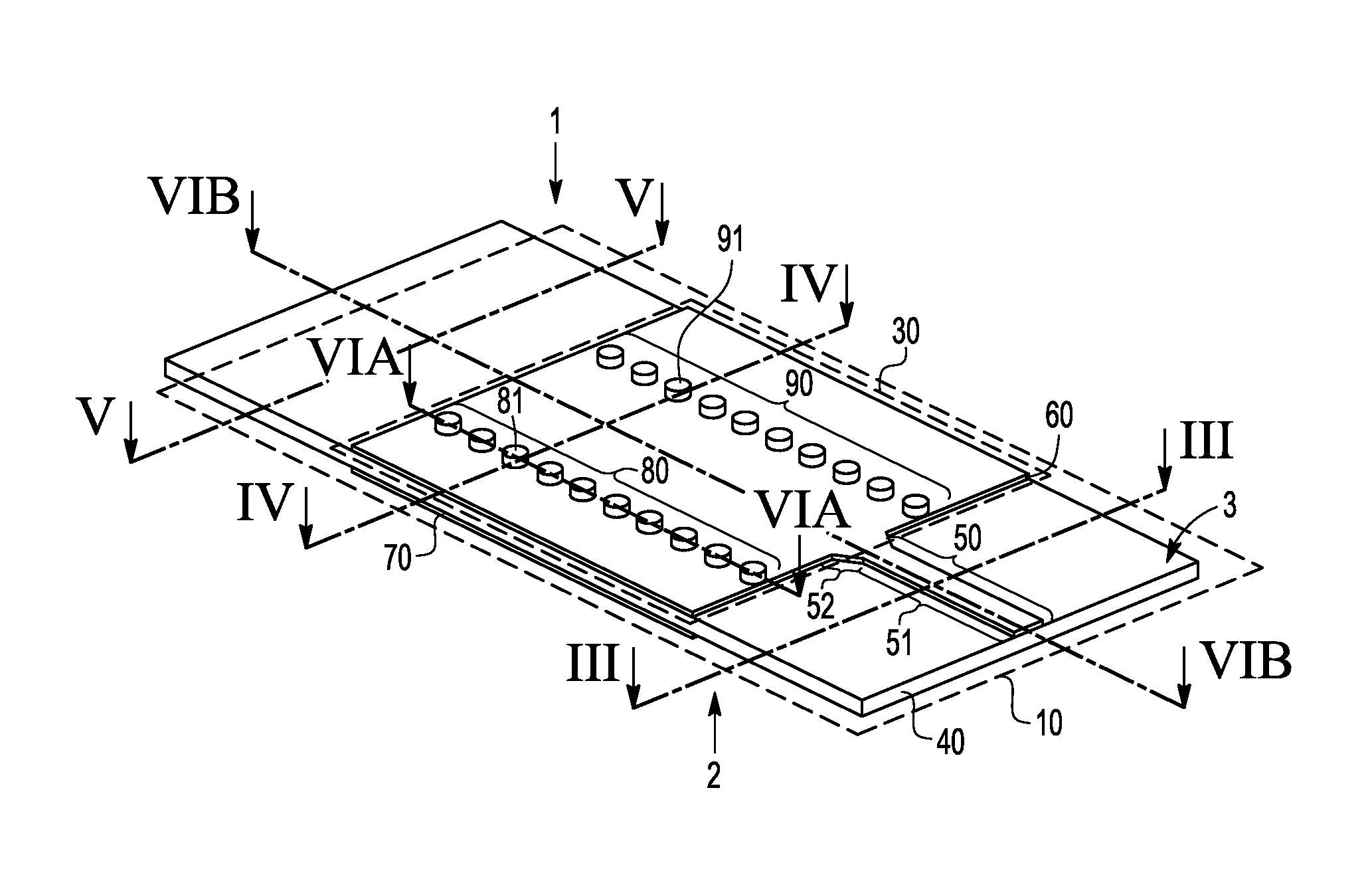
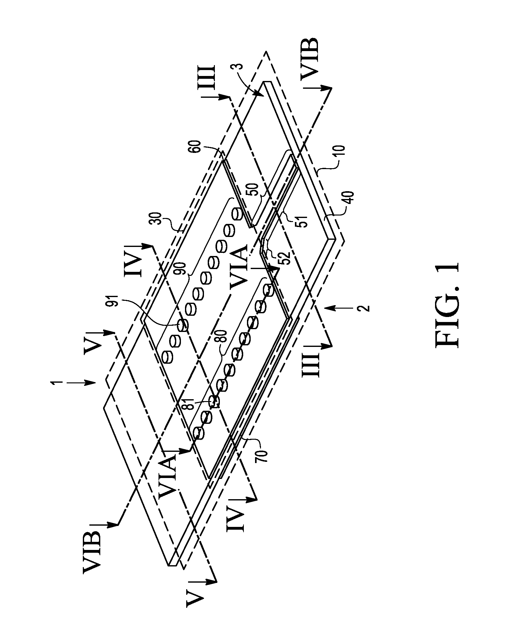
[0029]FIG. 1 schematically shows a perspective view of an example of a radio frequency (RF) coupling structure 10. The RF coupling structure 10 is arranged to couple a radio frequency signal between a first side 1 of the RF coupling structure 10 to a second side 2 of the RF coupling structure 10 opposite to the first side 1. For example, the RF coupling structure 10 may be arranged to couple the RF signal from the first side 1 to the second side 2. Alternatively or additionally, the RF coupling structure 10 may be arranged to couple the RF signal from the second side 2 to the first side 1. The RF coupling structure 10 comprises a dielectric layer 40 arranged between the first side 1 and the second side 2, a first electrically conductive layer 60 arranged on the dielectric layer 40 at the first side 1, a second electrically conductive layer 70 arranged on the dielectric layer 40 at the second side 2, and an integrated waveguide structure 30. The integrated waveguide structure 30 is f...


PUM


Abstract

A radio frequency coupling structure is arranged to couple a radio frequency signal between a first side of the radio frequency coupling structure to a second side of the radio frequency coupling structure opposite to the first side. The radio frequency coupling structure comprises a dielectric layer, a first electrically conductive layer comprising a first transition structure, a second electrically conductive layer comprising a second transition structure, and an integrated waveguide structure formed by an array of electrically conductive vias extending through the dielectric layer from the first to the second electrically conductive layer to enclose a portion of the dielectric layer. The portion is arranged to guide the radio frequency signal between the first transition structure and the second transition structure.

Description

FIELD OF THE INVENTION[0001]This invention relates to a radio frequency coupling structure, a multi-layer printed circuit board, a radio frequency device and a radar sensor.BACKGROUND OF THE INVENTION[0002]Radio frequency (RF) coupling structures may be used to transfer a RF signal from one side to another side of a RF device. The RF signal may for example be generated in an integrated circuit package and transferred to an external radiating structure. The RF signal may be attenuated during the transfer from the integrated circuit package to the external radiating structure in a way such that the RF signal may not be transmittable with sufficient strength. RF coupling structures may limit attenuations of the RF signal by matching at radio frequencies the integrated circuit package with the external radiating structure.[0003]Techniques are described in literature to enhance radio frequency coupling between an integrated circuit package and an external radiating structure.[0004]An exa...

Claims


Application Information

Patent Timeline
Patent Type & Authority Applications(United States)
IPC IPC(8): H01P3/02G01S13/02H01P1/201G01S13/931
CPCH01P3/026G01S13/02H01P1/2013G01S7/032H01P5/107H01Q13/06G01S13/931H01L2223/6677H01L2224/12105H01P5/028G01S7/028
Inventor TONG, ZIQIANGREUTER, RALF
Owner NXP USA INC
Why Eureka
Try Eureka