Lane boundary estimation device and lane boundary estimation method

a technology estimation device, which is applied in the field of lane boundary estimation device and lane boundary estimation method, can solve the problems of not producing a good template comparison, unable to detect solid lane boundary, such as a curb, and sometimes not being able to detect spatially continuous objects

Inactive Publication Date: 2015-12-24
TOYOTA JIDOSHA KK
View PDF0 Cites 16 Cited by
  • Summary
  • Abstract
  • Description
  • Claims
  • Application Information

AI Technical Summary

Benefits of technology

[0020]The lane boundary estimation device and the lane boundary estimation method in the first and second aspects of the present invention achieve the effect of reducing a situation in which a solid lane boundary in a distant area cannot be estimated.

Problems solved by technology

However, according to the related art, a solid lane boundary, such as a curb, cannot sometimes be detected as a spatially continuous object, for example, because a solid lane boundary, such as a curb, is not continuous at a position where there is a vehicle entrance / exit or because the solid lane boundary is hidden by other solid objects such as a telephone pole.
In such a case, the detection of a solid lane boundary based on level difference detection or based on template comparison is interrupted in the related art, sometimes with the result that a solid lane boundary in the distant area cannot be estimated.
The search for the neighboring distant area, if performed based on that template image, does not produce a good template comparison result, because the curb boundary within the solid frame (ii) includes a part where the curb is not continuous.
This makes the template comparison unstable, sometimes resulting in inaccurate position detection.
However, it is difficult to address this problem with these solutions because such a local texture change is difficult to predict.
If any of the positions described above is identified by the template generated in such a manner, there is still a possibility that the identified position cannot be confirmed as a correct road boundary.

Method used


Image

  • Lane boundary estimation device and lane boundary estimation method
  • Lane boundary estimation device and lane boundary estimation method
  • Lane boundary estimation device and lane boundary estimation method

Examples


first embodiment

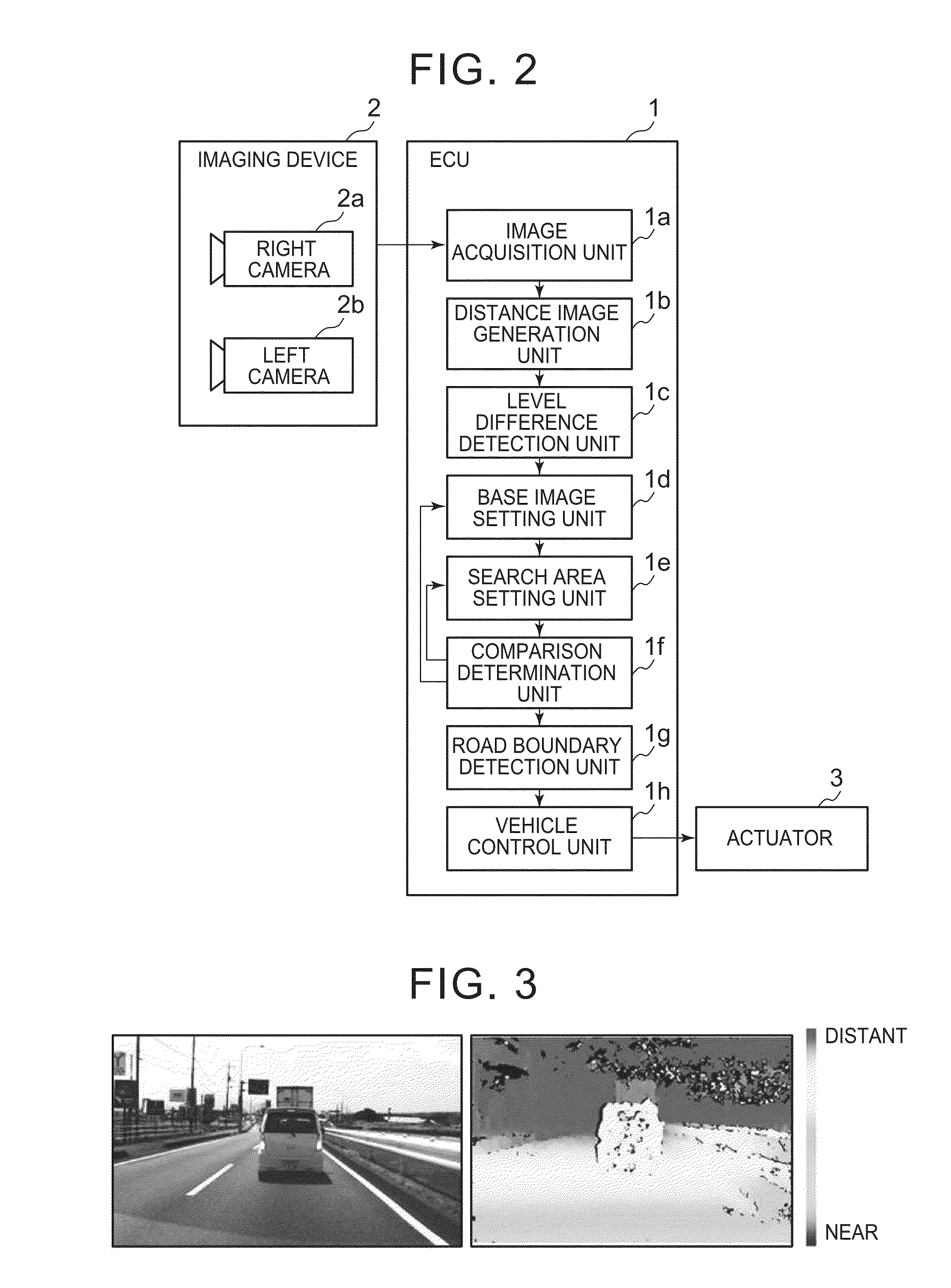
[0039]As shown in FIG. 2, the lane boundary estimation device in the first embodiment, mounted on a vehicle (host vehicle), typically includes an ECU 1, an imaging device 2, and an actuator 3.

[0040]The ECU 1, which controls the driving of the units of the vehicle, is an electronic control unit mainly configured by a microcomputer that includes the CPU, ROM, RAM, and interface. The ECU 1, electrically connected to the imaging device 2, receives the electrical signal corresponding to the detection result of the imaging device 2. The ECU 1 performs various types of arithmetic processing according to the electrical signal corresponding to the detection result. For example, the ECU 1 estimates a three-dimensional lane boundary (solid lane boundary), such as a curb, present in a lane based on the detection result of the imaging device 2. The ECU 1 outputs a control command, corresponding to the arithmetic processing result including the detection result of a solid lane boundary, to contro...

second embodiment

[0109]If template comparison is started from a search area that is set when the search area that is set is sufficiently near to the vehicle or when the solid lane boundary approaches the vehicle while skipping the search area, priority is placed on the estimation of the solid lane boundary performed through template comparison rather than on the estimation of the solid lane boundary based on the result of level difference detection in some case, regardless of the fact that the detection evaluation value detected through level difference detection is larger. However, even in such a situation, the detection method is switched appropriately in the second embodiment as described above according to the detection evaluation value for estimating the solid lane boundary.


PUM


Abstract

A lane boundary estimation device includes: a level difference detection unit detecting a first part of a solid lane boundary; a base image setting unit setting a first image area in a most distant area in the first part as a template image; a search area setting unit setting a search area from the most distant area; and a comparison determination unit detecting a boundary candidate point for a second part of the solid lane boundary by performing template comparison in the search area. When a detection evaluation value of the first part is lower than a predetermined value and the search area includes a low-evaluation search area, the base image setting unit re-sets a second image area, nearer to a vehicle than the low-evaluation search area, as the template image. The search area setting unit skips the low-evaluation search area and re-sets a new search area.

Description

INCORPORATION BY REFERENCE[0001]The disclosure of Japanese Patent Application No. 2014-129601 filed on Jun. 24, 2014 including the specification, drawings and abstract is incorporated herein by reference in its entirety.BACKGROUND OF THE INVENTION[0002]1. Field of the Invention[0003]The invention relates to a lane boundary estimation device and a lane boundary estimation method.[0004]2. Description of the Related Art[0005]Conventionally, a lane boundary estimation technology is reported.[0006]For example, Japanese Patent Application Publication No. 2013-161190 (JP 2013-161190 A) describes a technology that detects a three-dimensional lane boundary (solid lane boundary), such as a curb, in the direction from the near side to the distant side of the vehicle, based on the result of level difference detection that is performed for detecting a position, where there is a level difference, in the traffic environment around the vehicle. After that, the technology acquires the luminance imag...

Claims


Application Information

Patent Timeline
Patent Type & Authority Applications(United States)
IPC IPC(8): B60R1/00G06K9/62
CPCB60R1/00B60R2300/804G06K9/6202G06V20/647G06V20/588
Inventor TAKEMAE, YOSHINAOKIDONO, KIYOSUMI
Owner TOYOTA JIDOSHA KK
Why Eureka
Try Eureka