
Firearm-mounted camera device with networked control and administration system and method

a camera device and networked technology, applied in the field of networked system and electronic device of firearm, can solve the problems of not all police officers patrolling by, questions and taken for granted

Active Publication Date: 2015-12-24
CENTINEL SHIELD LLC
View PDF8 Cites 84 Cited by
  • Summary
  • Abstract
  • Description
  • Claims
  • Application Information

AI Technical Summary

Benefits of technology

The patent text describes a firearm-mounted electronic device that can chronicle events surrounding a hostile incident. The device is compact and mobile, and helps to save taxpayer resources by gathering available sensor data and enhancing review and management of cases and events related to firearms use. The technical effect of the patent is to provide a valuable tool for officers and others who need to quickly and accurately collect and analyze information in order to protect themselves and others from harm.

Problems solved by technology

Conversely, there are instances where a police officer's actions and motives are inappropriate, yet the self-serving statements made by a police officer about the course of events that transpired leading up to the fatal shooting are not questioned and taken for granted.
Moreover, while some patrol vehicles carry video cameras and recording equipment to monitor and chronicle events, such as at routine traffic stops, the observation equipment fitted on these vehicles typically focuses on what transpires directly in front of the vehicle, lacking the dynamic movement and viewpoint of the law enforcement official interacting with the passengers in a vehicle or with a suspect facing the police officer.
In addition, not all police officers patrol by car and many, especially in large metropolitan areas, are required to patrol on foot.

Method used


Image

  • Firearm-mounted camera device with networked control and administration system and method
  • Firearm-mounted camera device with networked control and administration system and method
  • Firearm-mounted camera device with networked control and administration system and method

Examples


Embodiment Construction

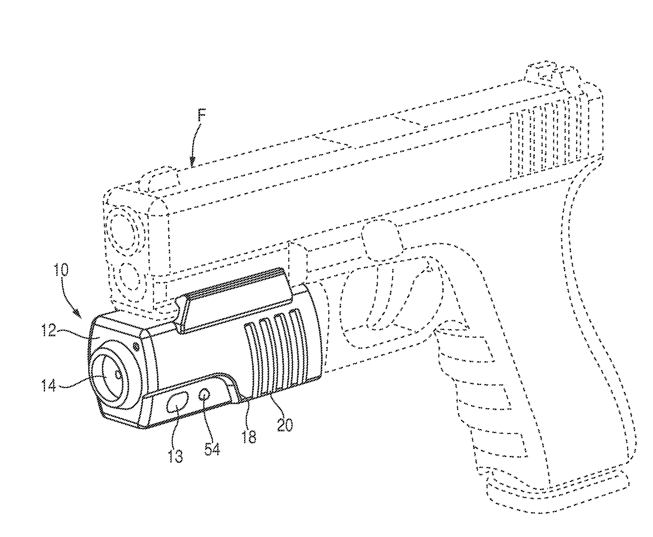
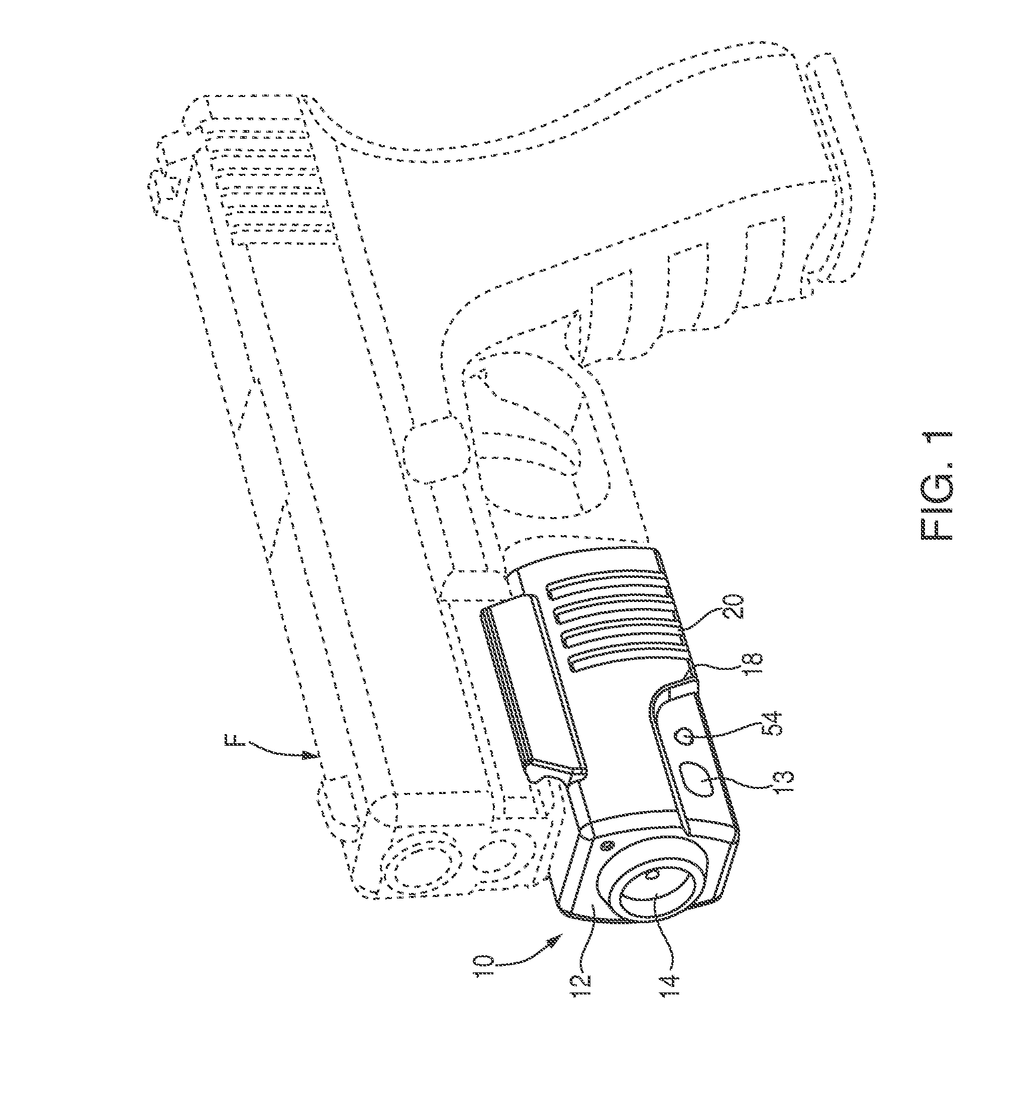
[0007]In view of the drawbacks and shortcomings of the prior art, it is a primary object of the present invention to provide a firearm-mounted electronic device and networked system and method that validate actions of law enforcement officials.

[0008]Another object of the present invention is to provide a firearm-mounted electronic device and networked system and method of identifying, isolating and gathering forensic evidence, such as video data, audio data, sensor data and other data, in connection with the use of a firearm by law enforcement officials.

[0009]It is a further object of the present invention to provide a firearm-mounted electronic device and networked system and method that chronicles events after the unholstering of a firearm and leading up to a hostile incident (e.g., shooting) to assist authorities and fact-finders in making determinations about whether actions taken by an individual carrying a firearm are justified or wrongful.

[0010]It is another object of the pre...


PUM

PropertyMeasurementUnit
heightaaaaaaaaaa
heightaaaaaaaaaa
latitudeaaaaaaaaaa

Abstract

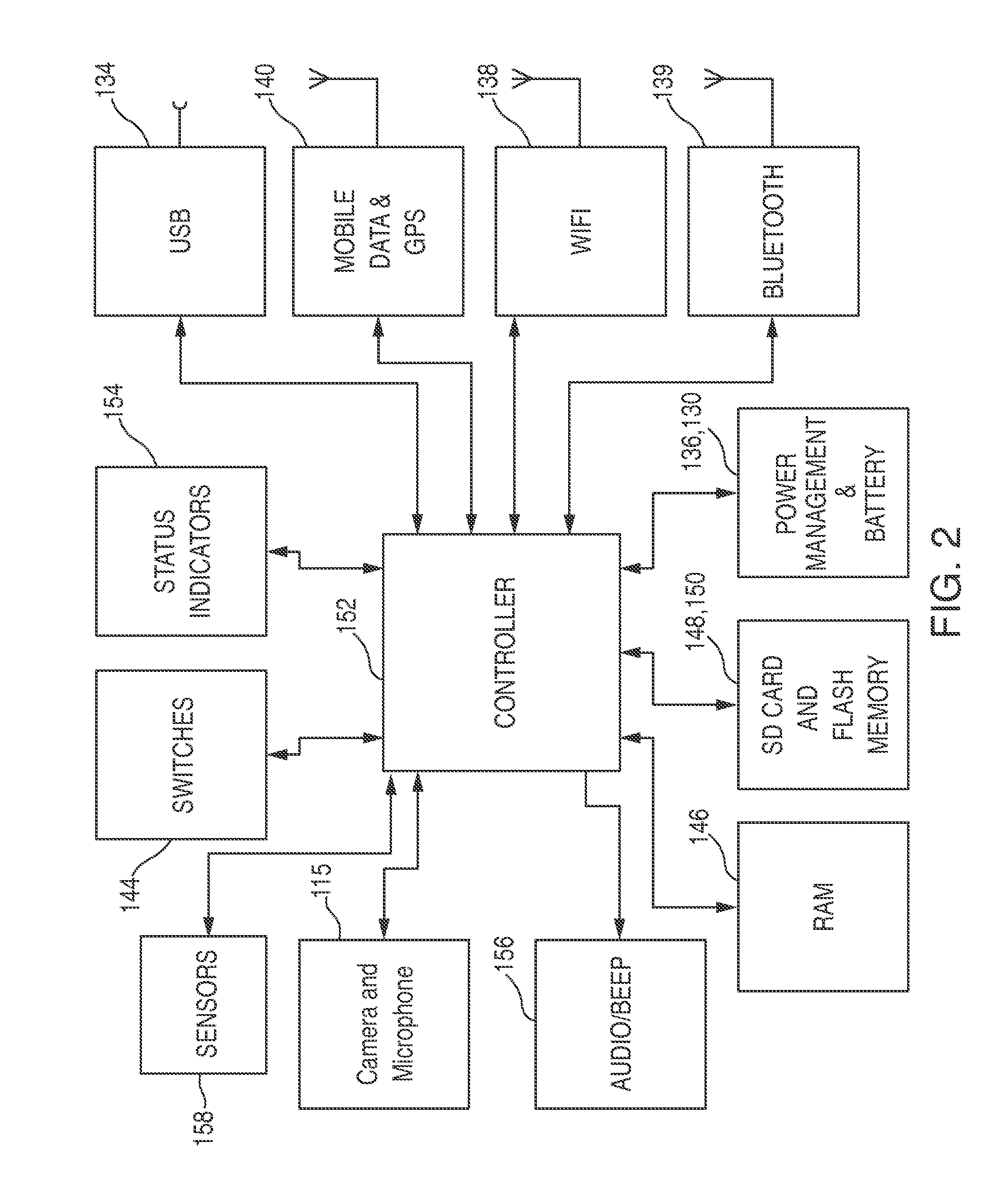
An electronic camera device, and associated system and interfaces, that generates, records and transmits video, audio and sensor data. Camera device comprises a housing with a fastening mechanism adapted to mount the device to a firearm. The device has a processor module, a memory module for storage, a camera module configured to generate and record video and store the video to memory. The device further includes a magnetic sensor configured to detect the presence and absence of a magnet and an accelerometer that is configured to detect a draw motion (e.g., a firearm being unholstered). When the magnetic sensor detects the absence of a magnet, and the accelerometer detects a draw motion, one or more corresponding signals are generated and transmitted, directing the camera to begin recording (and transmitting) video and send an alert signal to assets in the field to provide support.

Description

RELATED APPLICATIONS[0001]This application claims priority to U.S. provisional Application Ser. No. 62 / 013,596, filed on Jun. 18, 2014, and U.S. provisional Application Ser. No. 62 / 081,549, filed on Nov. 18, 2014, which are each incorporated herein by reference.FIELD OF THE INVENTION[0002]This invention relates to a firearm-mounted electronic device and networked system for detailing the position and movement of a firearm and other data associated therewith. More particularly, the invention involves a firearm-mounted camera device that transmits data relating to the firearm and use thereof, including video, audio, sensor data and other information, and which is operatively connected to an administration facility which controls and manages the camera device and cases, firearms, users and events associated with the camera device via graphical user interfaces generated by the system.BACKGROUND OF THE INVENTION[0003]Many acts of a lethal or non-lethal nature that are taken by police off...

Claims


Application Information

Patent Timeline
Patent Type & Authority Applications(United States)
IPC IPC(8): F41A17/06G08B13/196H04N21/2743G11B27/10F41C27/00H04N5/77
CPCF41A17/063F41C27/00H04N5/772G08B13/19673G11B27/10G08B13/19621H04N21/2743H04N5/77H04N5/907H04N9/8042H04N9/806H04N9/8205H04N7/183F41J5/10H04N23/57
Inventor KRAMER, MAXIMILIAN
Owner CENTINEL SHIELD LLC
Learn More