Cutting tool

a cutting tool and tool body technology, applied in the field of cutting tools, can solve the problems of poor versatility, high price of rechargeable batteries set to a large supply capacitance, etc., and achieve the effects of reducing vibration of cutting tools, increasing the weight of grip housings, and reducing the vibration of cutting tools

Active Publication Date: 2015-12-31
MAKITA CORP
View PDF5 Cites 32 Cited by
  • Summary
  • Abstract
  • Description
  • Claims
  • Application Information

AI Technical Summary

Benefits of technology

[0024]With this cutting tool, the grip housing may provided with at least one battery attachment portion allowing attachment of the rechargeable battery, and therefore, it is possible to attach the rechargeable battery to the at least one battery attachment portion. With the arrangement, it is possible to increase the weight of the grip housing having the handle portion, so that the vibrations generated through the reciprocation of the output shaft may be inhibited from being transmitted to the handle portion. Therefore, the cutting tool can be reduced in vibrations and can be improved in terms of feeling of use for the user.
[0025]Further, by the arrangement of the elastic member at at least a part between the front side portion of the grip housing and the rear side portion of the motor housing, the vibrations generated through the reciprocation of the output shaft may be transmitted to the handle portion via the elastic member, making it possible to buffer the vibrations transmitted to the handle portion. Therefore, the cutting tool can be reduced in vibrations and can be improved in terms of feeling of use for the user.

Problems solved by technology

However, a rechargeable battery set to a high voltage or a rechargeable battery set to a large supply capacitance is expensive and is poor in versatility.

Method used


Image

  • Cutting tool
  • Cutting tool
  • Cutting tool

Examples


first embodiment

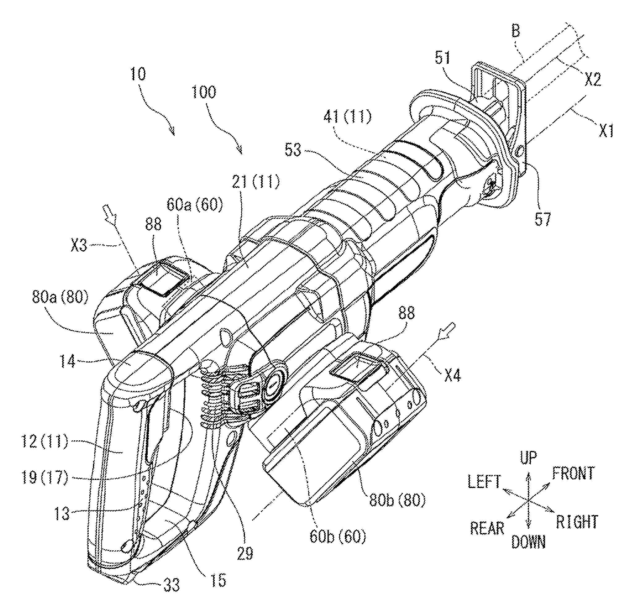
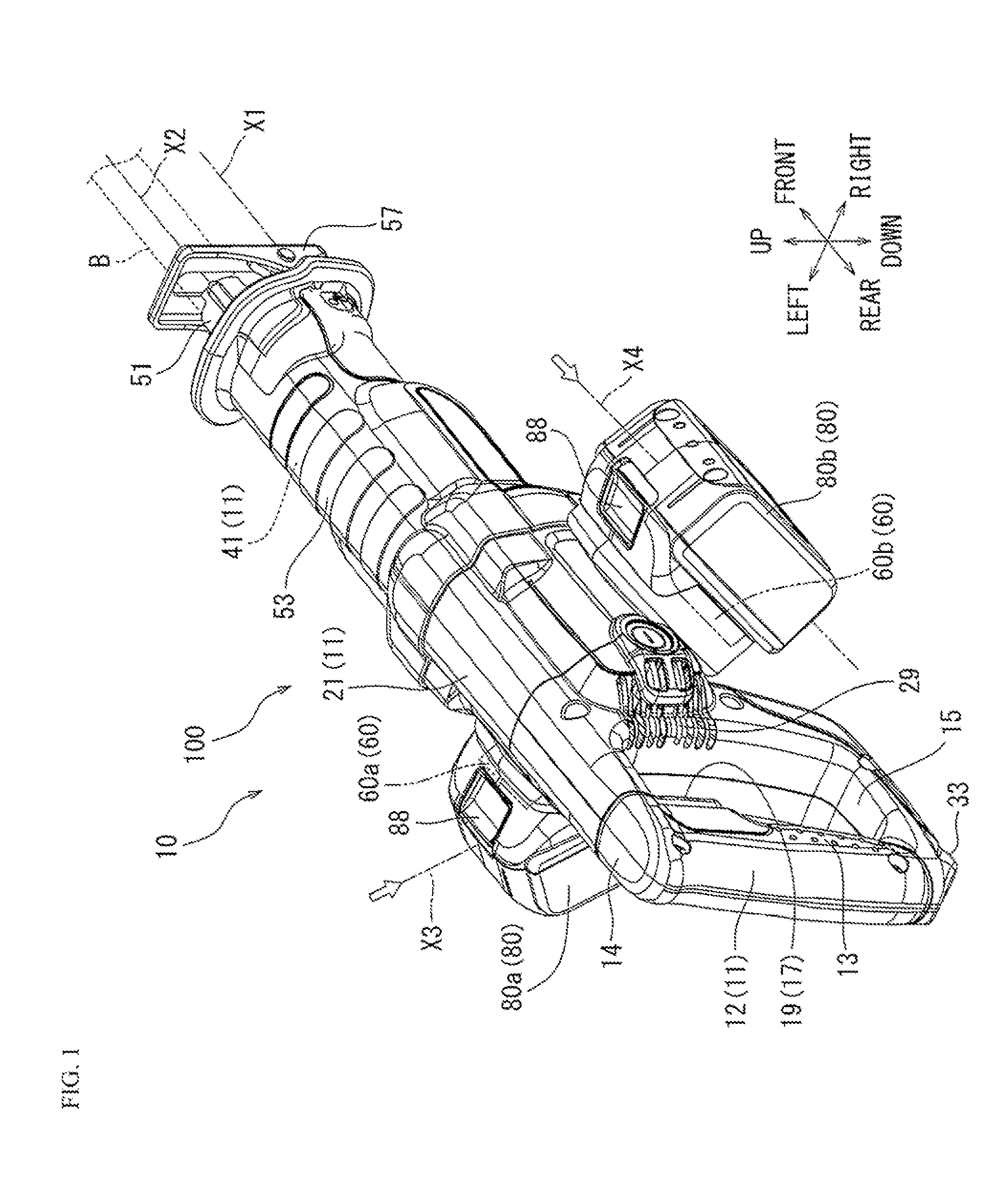
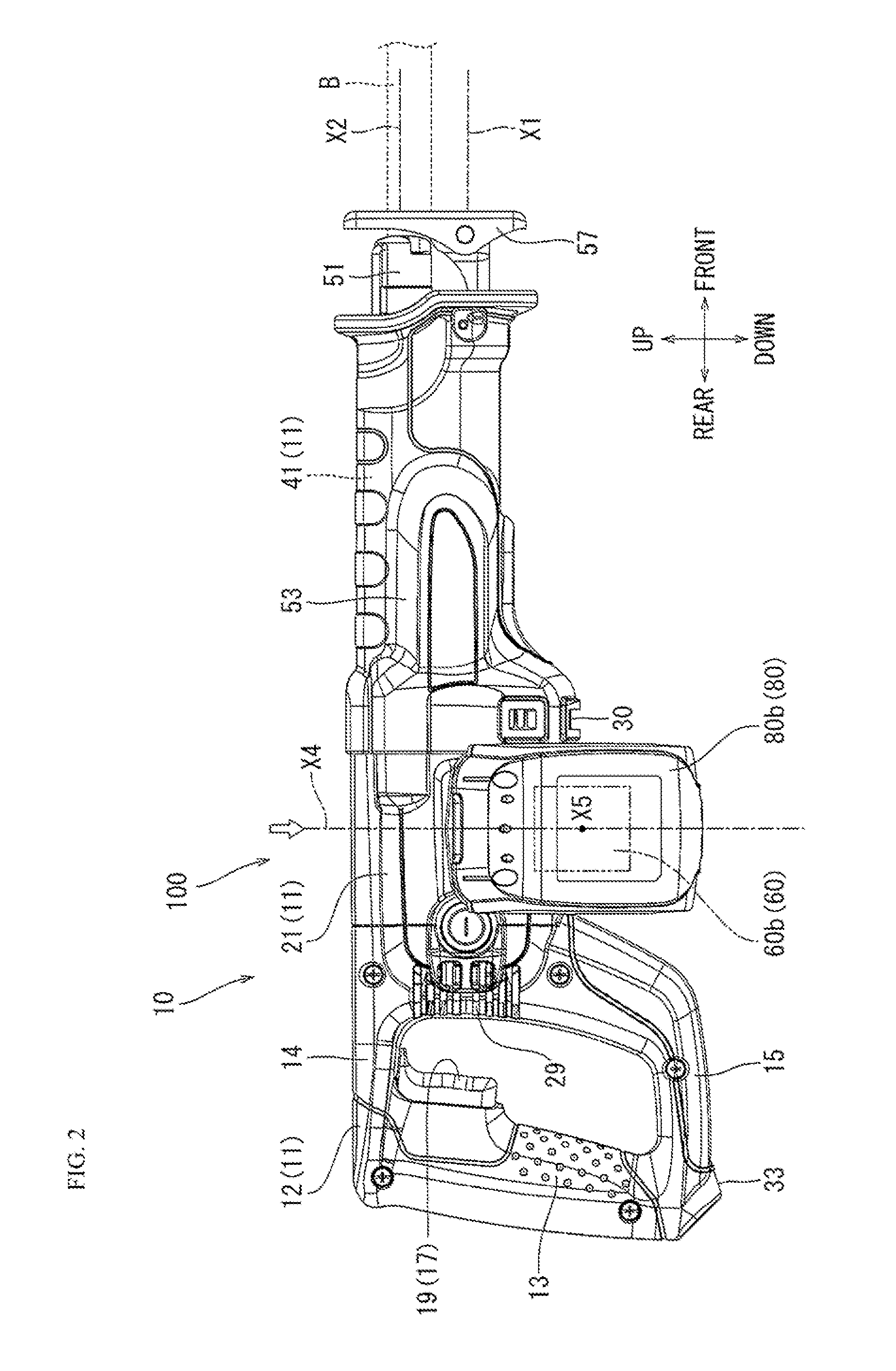
[0078]Next, a first embodiment will be described with reference to FIGS. 1 through 10. In FIG. 1, reference numeral 10 denotes a reciprocating saw which corresponds to a cutting tool according to the present invention. FIG. 1 is a substantially overall perspective view of the external appearance of the reciprocating saw 10 as seen obliquely from the rear side. FIG. 2 is a side view of the reciprocating saw 10 shown in FIG. 1. FIG. 3 is a plan view of the reciprocating saw 10 shown in FIG. 1 as seen from the rear side. FIG. 4 is a plan view of the reciprocating saw 10 shown in FIG. 1 as seen from the upper side. FIG. 5 is a sectional view taken along arrow line (V)-(V) of FIG. 4. FIG. 6 is a sectional view taken along arrow line (VI)-(VI) of FIG. 4. FIG. 7 is a substantially overall perspective view, as seen obliquely from the rear side, illustrating the external appearance of the reciprocating saw 10 with rechargeable batteries 80 removed therefrom. FIG. 8 is a plan view of the reci...

second embodiment

[0112]Next, second and third embodiments, which are modifications of the above-described first embodiment, will be described with reference to FIGS. 11 through 22. Reciprocating saws 10A and 10B of the second and third embodiments differ from the reciprocating saw 10 of the first embodiment only in the arrangement of the battery attachment portions 60. Thus, regarding the reciprocating saws 10A and 10B of the second and third embodiments, solely the arrangement different from the battery attachment portions 60 of the reciprocating saw 10 of the first embodiment will be described; the portions that are of the same construction as those of the first embodiment are labeled with the same reference numerals, and a description thereof will be omitted.

[0113]The reciprocating saw 10A according to the second embodiment may be constructed as illustrated in FIGS. 11 through 16.

[0114]The reciprocating saw 10A of the second embodiment differs from the reciprocating saw 10 of the first embodiment...

third embodiment

[0117]Next, the third embodiment will be described. The reciprocating saw 10B according to the third embodiment may be constructed as shown in FIGS. 17 through 22.

[0118]The reciprocating saw 10B according to the third embodiment differs from the reciprocating saw 10 of the second embodiment in the orientation in which the rechargeable batteries 80a and 80b are attached to battery attachment portions 60Ba and 60Bb through sliding. More specifically, lower surfaces 800a and 800b of the rechargeable batteries 80a and 80b attached to the battery attachment portions 60Aa and 60Ab of the second embodiment extend in directions inclined with respect to the right-left direction of the tool main body 100B.

[0119]In contrast, the lower surfaces 800a and 800b of the rechargeable batteries 80a and 80b attached to the battery attachment portions 60Ba and 60Bb of the third embodiment extend in a direction in conformity with the right-left direction of the tool main body 100B. That is, as shown in F...


PUM

PropertyMeasurementUnit
voltageaaaaaaaaaa
power voltageaaaaaaaaaa
voltageaaaaaaaaaa

Abstract

A motor housing of housings forming an outer casing of a tool main body is provided with two battery attachment portions allowing attachment of rechargeable batteries. The two battery attachment portions are configured as slide attachment type battery attachment portions. The two battery attachment portions are suited to slide attachment type rechargeable batteries that are attached through sliding. The two rechargeable batteries are attached in the right-left direction of the tool main body so that the two rechargeable batteries can be arranged side by side in the direction in which the tool main body extends.

Description

TECHNICAL FIELD[0001]The embodiments of the present disclosure relate to a cutting tool that may be configured to reciprocate an elongated cutting blade for cutting a workpiece.BACKGROUND ART[0002]As a cutting tool for cutting a workpiece such as wood, there has been known a cutting tool called a reciprocating saw (see, for example, Japanese Laid-Open Patent Publication No. 2012-51046). This type of reciprocating saw is configured as a hand-held type cutting tool for performing a cutting operation while being held by hand. In brief, this type of reciprocating saw is provided with a housing, an electric motor housed in the housing, and a reciprocation converting mechanism that converts the rotational drive force of the electric motor to a reciprocating motion.[0003]A cutting blade mounting mechanism is provided at the output shaft of the reciprocation converting mechanism. Mounted to this cutting blade retaining mechanism is an elongated blade (cutting blade) extending in the recipro...

Claims


Application Information

Patent Timeline
Patent Type & Authority Applications(United States)
IPC IPC(8): B23D49/16B25F5/02B23D51/10
CPCB23D49/162B23D51/00B23D51/10B23D49/16B25F5/02B25F5/006
Inventor UKAI, TOMOHIROTAHARA, TAKAYUKIUKAI, TAISUKESUGINO, YUDAI
Owner MAKITA CORP
Why Eureka
Try Eureka