Lock for Retaining Minidisks with Rotors of a Gas Turbine Engine

Active Publication Date: 2015-12-31
RAYTHEON TECH CORP
View PDF3 Cites 37 Cited by
  • Summary
  • Abstract
  • Description
  • Claims
  • Application Information

AI Technical Summary

Benefits of technology

[0007]In accordance with one aspect of the disclosure, a rotor is disclosed. The rotor may include a disk having a central axis, a plurality of airfoils radially extending from the disk, a bayonet tab extending radially from the disk

Problems solved by technology

While effective, these separate joints increase the we

Method used


Image

  • Lock for Retaining Minidisks with Rotors of a Gas Turbine Engine
  • Lock for Retaining Minidisks with Rotors of a Gas Turbine Engine
  • Lock for Retaining Minidisks with Rotors of a Gas Turbine Engine

Examples


Embodiment Construction

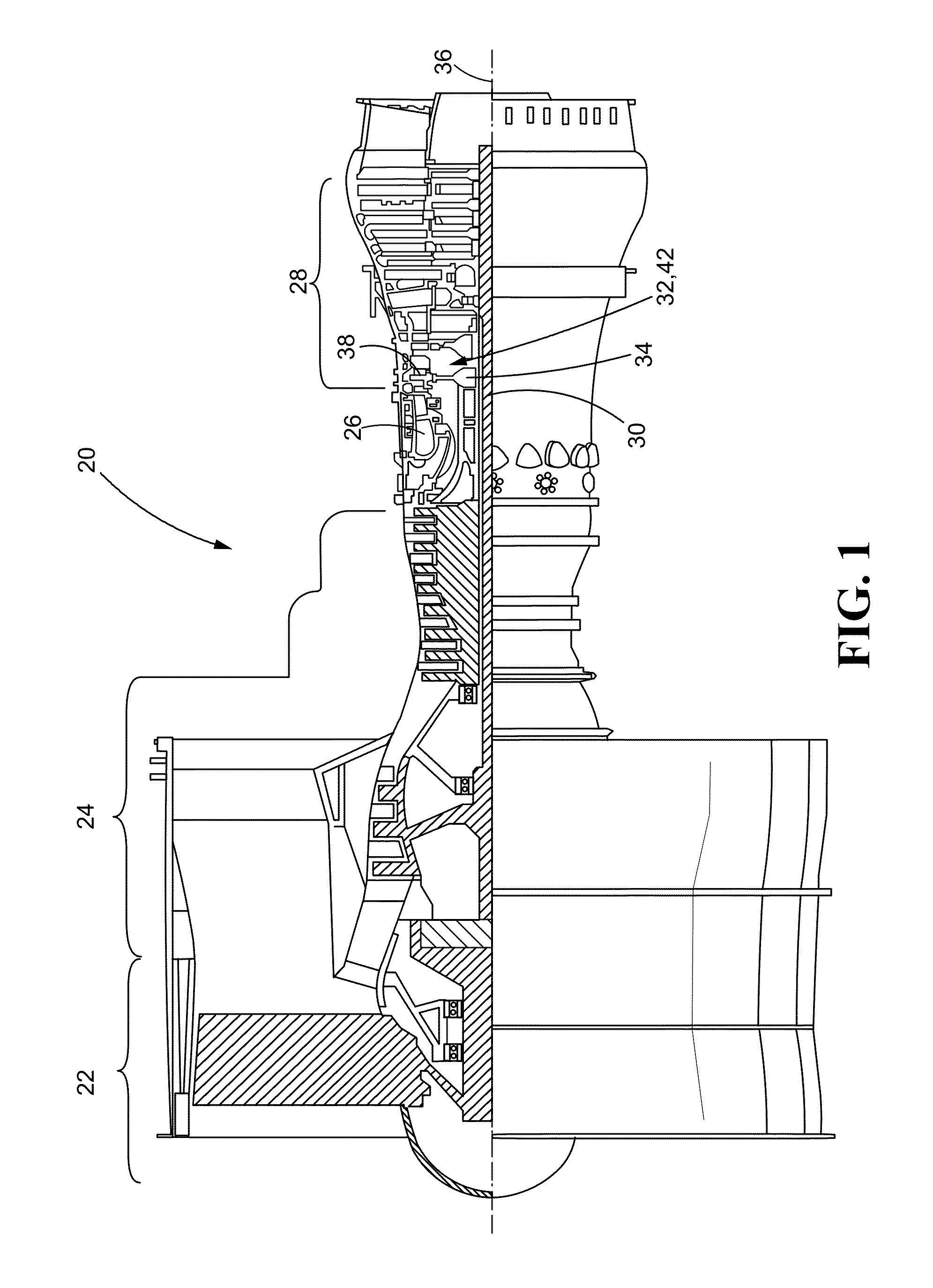
[0042]Referring now to the drawings, and with specific reference to FIG. 1, a gas turbine engine 20 is illustrated. Gas turbine engines 20 typically include a plurality of axially aligned components, such as a fan 22, a compressor 24, a combustor 26, and a turbine 28. Ambient air is drawn in and accelerated by the fan 22 before flowing downstream to the compressor 24 to be compressed. The compressed air flows further downstream and is combined with a fuel and combusted at the combustor 26 forming an exhaust. The exhaust flows downstream from the combustor 26 to the turbine 28 where the exhaust expands, causing the turbine 28 to rotate. This rotational motion is transferred to the fan 22 and compressor 24 via an engine shaft 30 extending axially through the engine 20. The engine 20 illustrated in FIG. 1 is a dual spool engine having a high pressure and low pressure compressor 24 and turbine 26, each of which are linked by a separate engine shaft 30. This is only one possible configur...


PUM

PropertyMeasurementUnit
Lengthaaaaaaaaaa
Flow rateaaaaaaaaaa
Widthaaaaaaaaaa

Abstract

In accordance with one aspect of the disclosure, a rotor is disclosed. The rotor may include a disk having a central axis, an airfoil radially extending from the disk, a bayonet tab extending radially from the disk, and a lock. The lock may further include a short tab and a long tab, both extending radially from the disk and in an axial direction with respect to the central axis. The long tab may have a greater axial length than the short tab.

Description

CROSS-REFERENCE TO RELATED APPLICATION[0001]This patent application is a US National Stage under 35 U.S.C. §371, claiming priority to International Application No. PCT / US2013 / 075993 filed on Dec. 18, 2013, which claims priority under 35 U.S.C. §119(e) to U.S. Patent Application Ser. No. 61 / 798,933 filed on Mar. 15, 2013.FIELD OF THE DISCLOSURE[0002]The present disclosure generally relates to gas turbine engines and, more specifically, to locking mechanisms for rotors and their associated minidisks.BACKGROUND OF THE DISCLOSURE[0003]A gas turbine engine, typically used as a source of propulsion in aircraft, operates by drawing in ambient air, combusting that air with a fuel, and then forcing the exhaust from the combustion process out of the engine. In many gas turbine engines, a fan rotates to draw air into the engine; however, the fan is not a necessity for all gas turbine engines. A compressor section is disposed axially downstream of the fan and includes a plurality of axially ali...

Claims


Application Information

Patent Timeline
IPC IPC(8): F01D5/32F01D11/00F01D5/12F01D5/30F02C3/04F01D5/02
CPCF01D5/082F01D5/3015F01D5/02F05D2220/32F02C3/04Y02T50/676F01D5/32F01D5/3046F01D5/12F05D2230/60F01D11/006Y02T50/60F05D2260/33
Inventor PARTYKA, JULIANSANDOVAL, JONATHAN PERRY
Owner RAYTHEON TECH CORP
Why Eureka
Try Eureka