Sensor system with a three half-bridge configuration

a sensor system and half-bridge technology, applied in the field of sensor systems, can solve the problems of low accuracy, low sensitivity of hall sensors and mts, and low accuracy of lorenz force, and achieve low cost of production and/or operation, low noise, and reliable output of low-amplitude signals

Active Publication Date: 2015-12-31
NXP BV
View PDF33 Cites 21 Cited by
  • Summary
  • Abstract
  • Description
  • Claims
  • Application Information

AI Technical Summary

Benefits of technology

[0007]There may be a need for providing a sensor system and a method for sensing a physical quantity, which on the one hand produce are reliable and low-noise signal output and on the other hand require low costs for production and / or operation.

Problems solved by technology

Hall sensors and MTs, which rely on the Lorenz force, have a comparatively low sensitivity and consequently also a low accuracy.
However, such AMR sensor systems suffer from output signals which have only low amplitudes and which are typically very noisy.
However, such AMR sensor systems are suffering from an additional effort in size, current consumption and costs.

Method used


Image

  • Sensor system with a three half-bridge configuration
  • Sensor system with a three half-bridge configuration

Examples


Embodiment Construction

[0059]The illustration in the drawing is schematically. It is noted that spatially relative terms, such as “front” and “back”, “above” and “below”, “left” and “right”, et cetera are used to describe an element's relationship to another element(s) as illustrated in the FIGURES. Thus, the spatially relative terms may apply to orientations in use which differ from the orientation depicted in the FIGURE. Obviously, though, all such spatially relative terms refer to the orientation shown in the FIGURE for ease of description and are not necessarily limiting as a system according to an embodiment of the invention can assume orientations different than those illustrated in the FIGURE when in use.

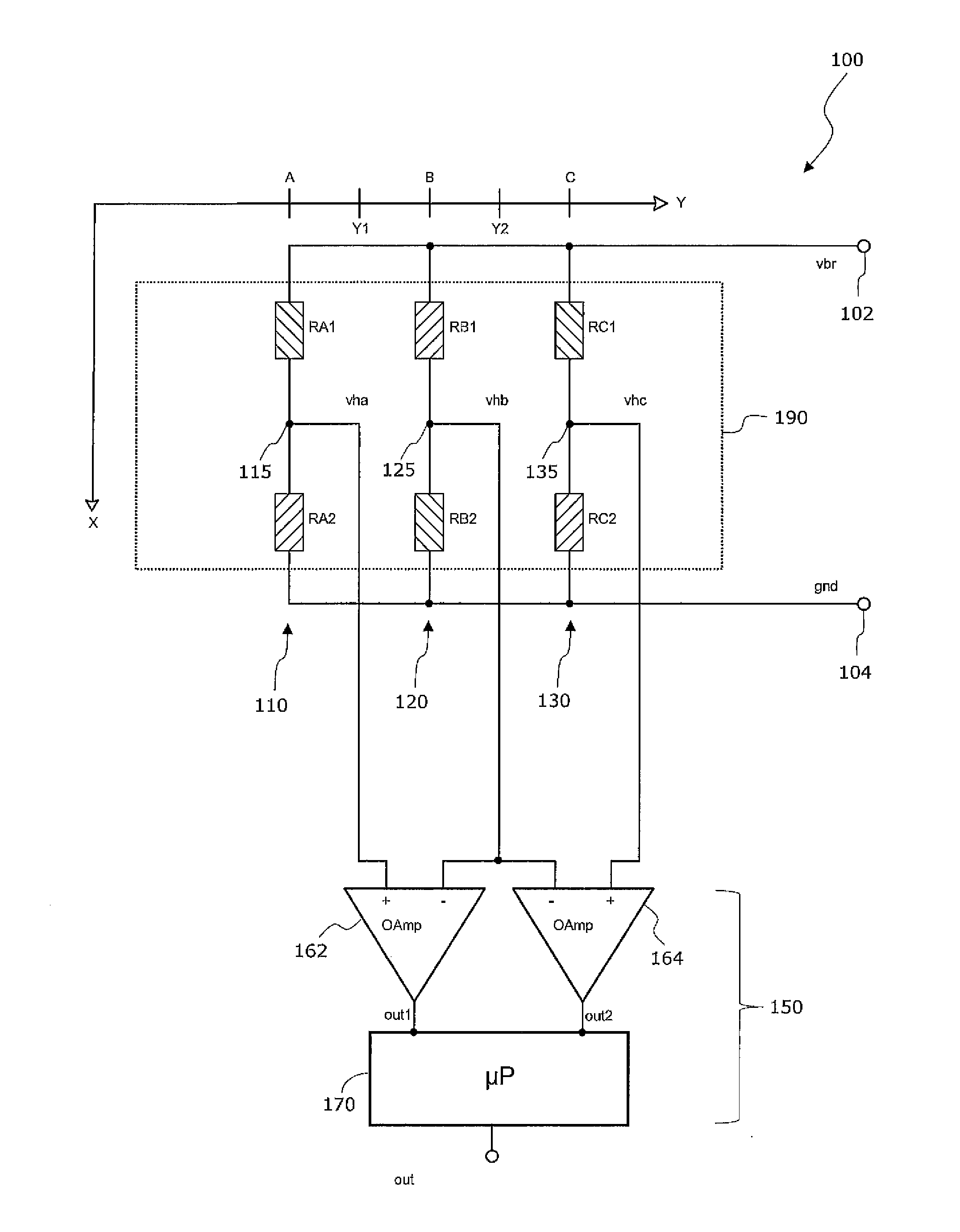
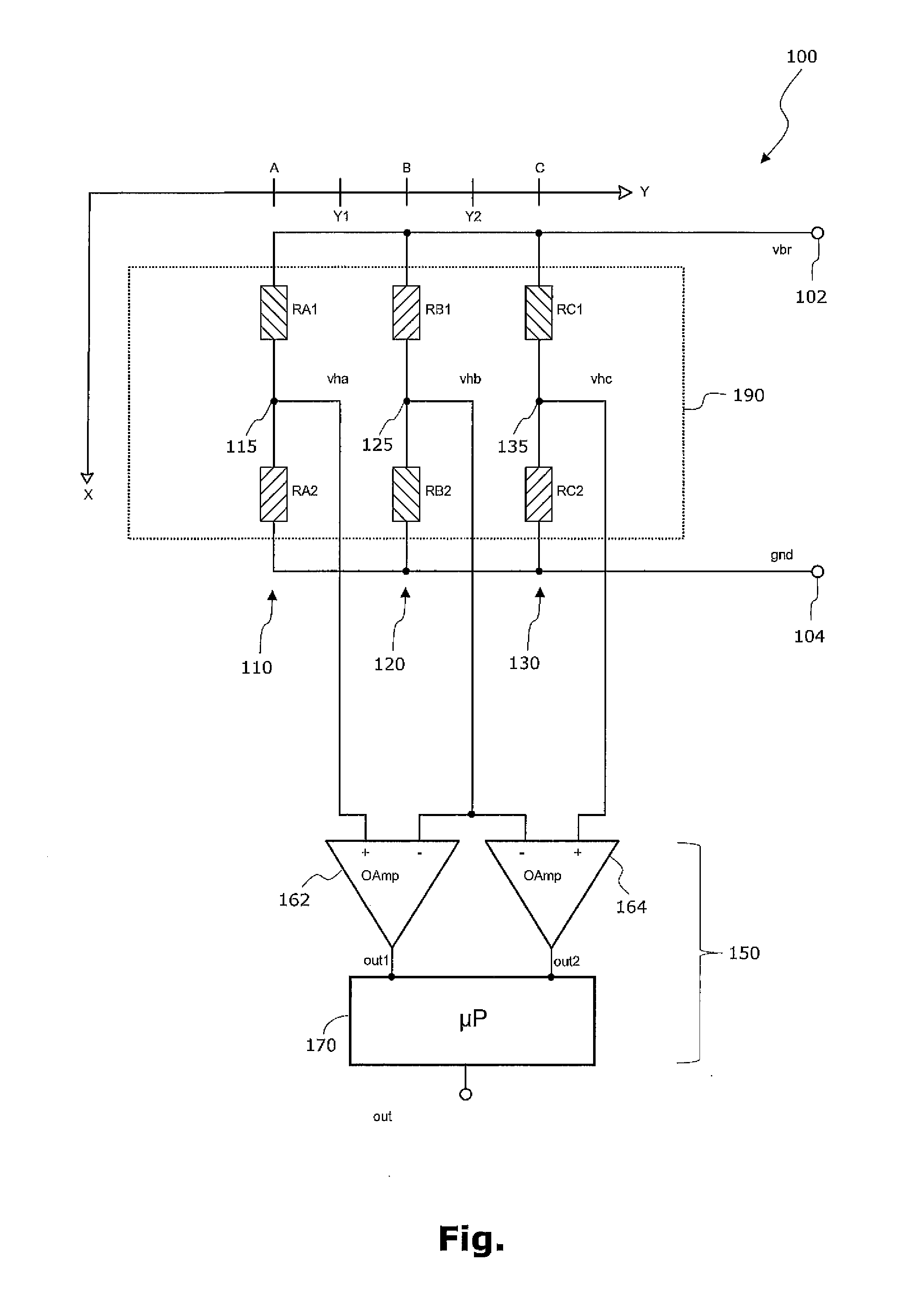
[0060]FIG. 1 shows in accordance with a presently preferred embodiment of the invention a magnetic sensor system 100 which comprises a sensing configuration. This sensing configuration consists of three sensing paths 110, 120 and 130. As can be seen from the FIGURE, each sensing path comprises (i) ...


PUM


Abstract

It is described a sensor system (100) and a method for sensing a physical quantity. The sensor system (100) comprises (a) a first sensor path (110) comprising a first first sensing element (RA1) and a second first sensing element (RA2) being connected in series between a first supply terminal (102) and a second supply terminal (104) and a first intermediate node (115) being provided in between the first first sensing element (RA1) and the second first sensing element (RA2); (b) a second sensor path (120) comprising a first second sensing element (RB1) and a second second sensing element (RB2) being connected in series between the first supply terminal (102) and the second supply terminal (104) and a second intermediate node (125) being provided in between the first second sensing element (RB1) and the second second sensing element (RB2); (c) a third sensor path (130) comprising a first third sensing element (RC1) and a second third sensing element (RC2) being connected in series between the first supply terminal (102) and the second supply terminal (104) and a third intermediate node (135) being provided in between the first third sensing element (RC1) and the second third sensing element (RC2); and (d) a signal processing device (150), which is connected with the first intermediate node (115), the second intermediate node (125) and the third intermediate node (135) and which is configured for processing, based on (a) a first electric variable (vha) being given at the first intermediate node (115), (b) a second electric variable (vhb) being given at the second intermediate node (125), and (c) a third electric variable (vhc) being given at the third intermediate node (135), an output signal (out) being indicative for the sensed physical quantity.

Description

FIELD OF THE INVENTION[0001]The present invention relates to a sensor system having resistive sensing elements, wherein respectively two resistive sensing elements are connected in series in a sensor path of a bridge configuration. Specifically, the present invention relates to a sensor system and a method for sensing a physical quantity, in particular a magnetic field and a time dependency of a magnetic field.BACKGROUND OF THE INVENTION[0002]Magnetic sensor systems are increasingly important in various industries. For instance in the automotive industry various sensor systems such as parking sensors, angular sensors e.g. in throttle valves, ABS (Automatic Braking System) sensors and tire pressure sensors can be found in modern vehicles for improving comfort and safety. Magnetic sensor systems are particularly important in automotive applications, because magnetic fields penetrate easily through most materials. Magnetic sensors are also highly insensitive to dirt, unlike for example...

Claims


Application Information

Patent Timeline
Patent Type & Authority Applications(United States)
IPC IPC(8): G01D5/14
CPCG01D5/14G01R33/09G01R33/0029G01R33/0023
Inventor MEYER, ROBERTPREISNER, THOMASSCHOENEICH, MICHAEL
Owner NXP BV
Why Eureka
Try Eureka