Flow field plate for a fuel cell

Active Publication Date: 2015-12-31
POWERCELL SWEDEN AB
View PDF2 Cites 3 Cited by
  • Summary
  • Abstract
  • Description
  • Claims
  • Application Information

AI Technical Summary

Benefits of technology

[0031]According to a further preferred embodiment, the bipolar plate assembly is shaped asymmetrically, wherein the fuel manifold is smaller than the oxidant manifold and/or wherein the cooling fluid sub-manifold of the anode plate is larger than the cooling fluid sub-manifold of the cathode plate), and/or wherein the oxidant flow field of the cathode plate comprises more channel-like structures than the fuel flow field of the anode plate, and/or wherein a cross-section of the channel-like structures of the fuel flow field of the anode plate is smaller than a cross-section of the channel-like structures of the oxidant flow field of the cathode plate. Thereby, a bip

Problems solved by technology

Disadvantageously, the cooling provided b the simple prolongation of the cooling channels is not sufficient for controlling the temperature during situations, where the anode gas and the cathode gas are significantly cooler or hotter than a specified temperature range.
This deviation in temperature can, if not carefully controlled by additional components,

Method used


Image

  • Flow field plate for a fuel cell
  • Flow field plate for a fuel cell
  • Flow field plate for a fuel cell

Examples


Embodiment Construction

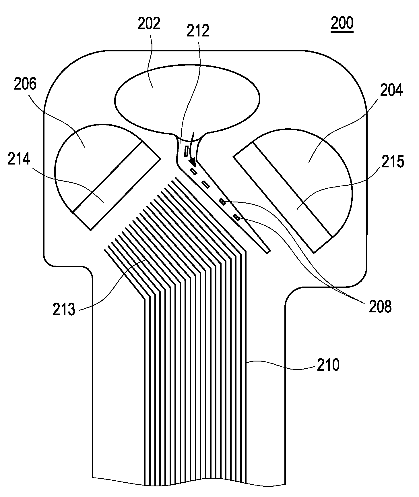
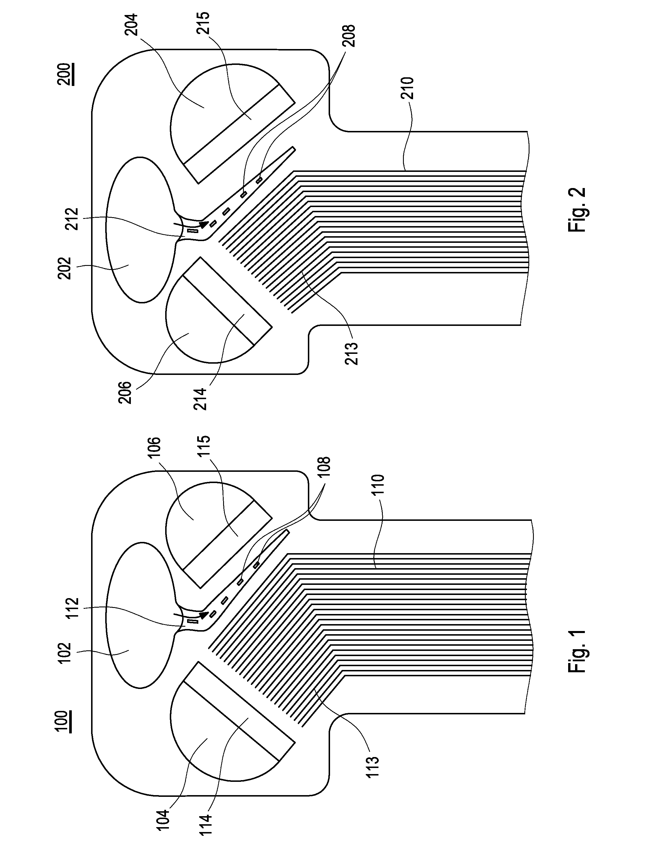
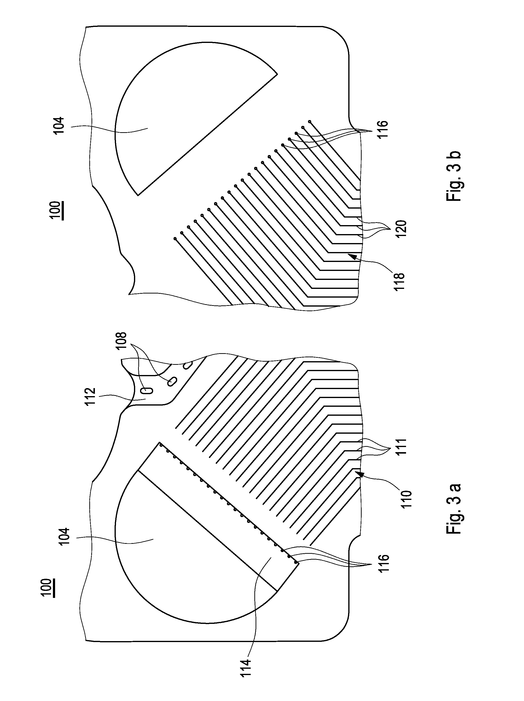
[0042]In the following same or similarly acting elements are indicated by the same reference numerals.

[0043]In general, a fuel cell stack is built by stacking a plurality of repeating fuel cell units between two end assembly units that hold the stacked cells together. The repeating fuel cell units comprise mainly two sub-assemblies, namely a 5-layer membrane electrode assembly (5-laver MEA) and a bipolar plate assembly. Optionally, a sealing layer may be arranged between the 5-layer MEA. and the bipolar plate assembly sealing both main components. The sealing layer may also be an integral part of the 5-layer MEA and / or of the bipolar plate assembly.

[0044]The 5-layer MEA comprises a membrane electrode assembly covered on both sides by a gas diffusion layer. The membrane electrode assembly itself comprises a membrane with two electrodes, an anode and a cathode, placed on the two major surfaces of the membrane. The anode (electrode) and the cathode (electrode) are covered by the gas di...


PUM


Abstract

A flow field plate for a bipolar plate or bipolar plate assembly of a fuel cell or a fuel cell stack has an electrode facing front side, a backside and at least a cooling fluid manifold for supplying cooling fluid to the flow field plate. The backside includes a cooling fluid flow field for substantially uniformly distributing the cooling fluid over the flow field, plate. The flow field plate further includes a cooling fluid sub-manifold which is adapted to provide cooling fluid from the cooling fluid manifold to a cooling fluid flow field. The cooling fluid sub-manifold is fluidly disconnected from the cooling fluid flow field, a bipolar plate or bipolar plate assembly including a flow field plate, as well as a fuel cell or fuel cell stack including such a flow field plate and/or bipolar plate or such a bipolar plate assembly.

Description

BACKGROUND AND SUMMARY[0001]The present invention relates to a flow field plate, particularly for a bipolar plate of a fuel cell or a fuel cell stack, a bipolar plate assembly for a fuel cell and a fuel cell or fuel cell stack comprising such a flow field plate and / or such a bipolar plate or bipolar plate assembly.[0002]Usually fuel cells are arranged in fuel cell stacks which are built by stacking a plurality of repeating unit fuel cells between two end assembly units, which hold the stacked cells together. In the fuel cell stack there are features for distributing various fluids (reactants, cooling fluid) over the fuel cell stack. The features are called manifolds and flow fields. The features conducting fresh reactants and fresh cooling fluid are called inlet manifolds and the features removing unused reactants and products as well as outgoing cooling fluids are called outlet manifolds. For distributing the various fluids over active areas in the fuel cell, flow fields are used w...

Claims


Application Information

Patent Timeline
IPC IPC(8): H01M8/02H01M8/04
CPCH01M8/241H01M8/0258H01M8/0267H01M2008/1095H01M8/04074H01M8/2483Y02E60/50
Inventor BODÈN, ANDREASTINGELÖF, THOMASOFSTAD, AXEL BAUMANNIHONEN, JANTENSTAM, ANDERS
Owner POWERCELL SWEDEN AB
Why Eureka
Try Eureka