Undulating stator for reducing the noise produced by interaction with a rotor

Active Publication Date: 2016-01-07
SN DETUDE & DE CONSTR DE MOTEURS DAVIATION S N E C M A
View PDF2 Cites 11 Cited by
  • Summary
  • Abstract
  • Description
  • Claims
  • Application Information

AI Technical Summary

Benefits of technology

[0008]An object of the present disclosure is, among others, to reduce efficiently the tonal noise caused by the interaction of the s

Problems solved by technology

The passage of the air on the structures of the engine causes fluctuating pressure disturbances which are propagated, and form sources of noise which are a nuisance for the environment.
In particular, the noise which is propagated in the air inlet duct of a bypass turbojet is caused almost entirely by the fan.
In addition, the main source of tonal noise is generally the interaction between the fan and stator elements, whereas the broadband noise is caused in particular by turbulence.
The source of tonal noise is mainly the result of the periodic impact of the wake of the blades of the fan rotor on the fins.
However, this solution makes it necessary to have a certain thickness in the stator.
It is

Method used


Image

  • Undulating stator for reducing the noise produced by interaction with a rotor
  • Undulating stator for reducing the noise produced by interaction with a rotor
  • Undulating stator for reducing the noise produced by interaction with a rotor

Examples


Embodiment Construction

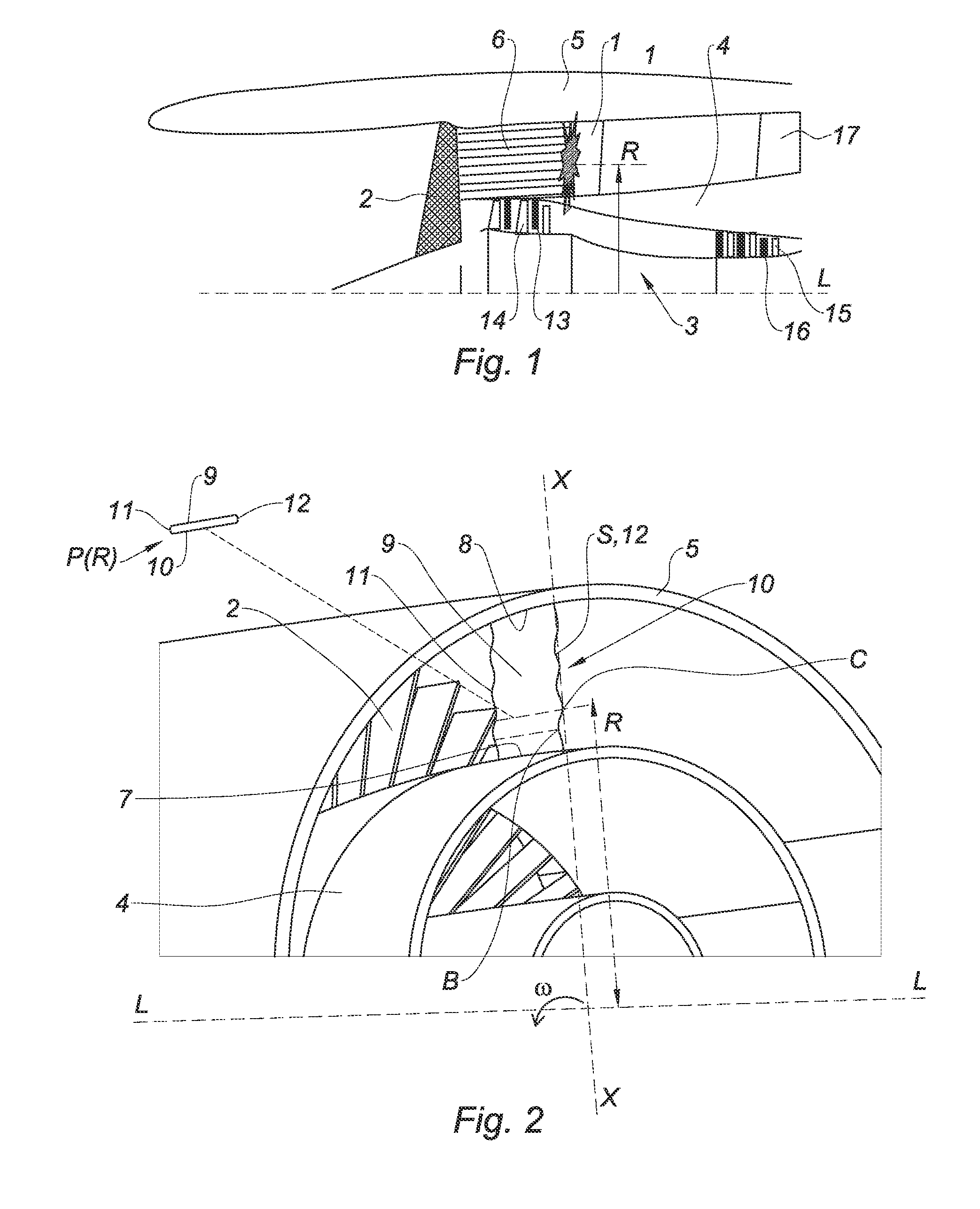
[0033]With reference to FIG. 1, examples of the present disclosure relate to stators formed by OGV fins 1 or fixed vanes placed in the secondary flow driven by the blades 2 of a turbine engine fan, rotating about the axis LL of rotation of an engine 3.

[0034]The fins 1 pass radially through the stream of the secondary flow, from the outer casing 4 of the engine 3 to the nacelle 5. As illustrated in FIG. 1, each fin 1 is periodically impacted by the wake 6 of each blade 2 of the fan.

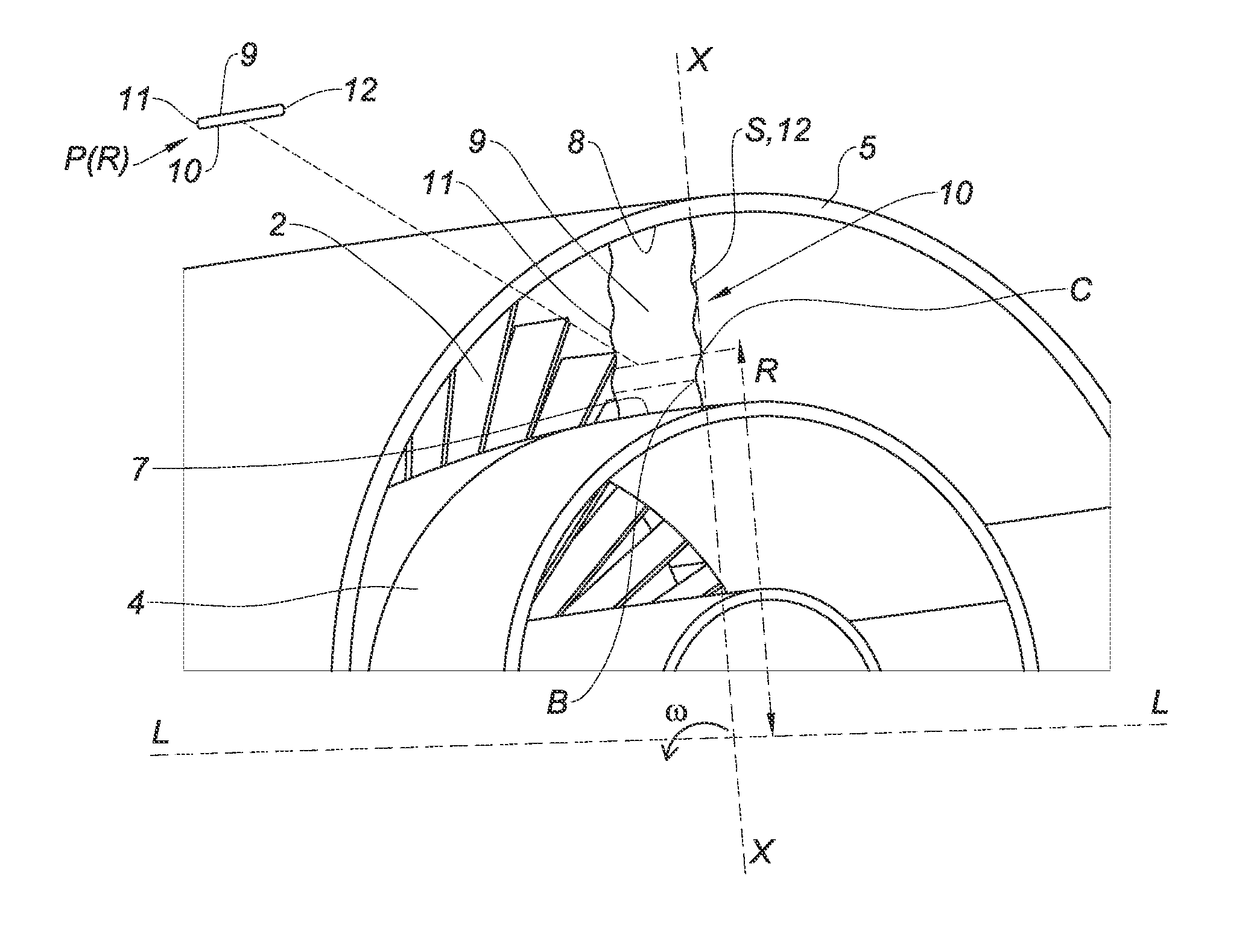
[0035]With reference to FIG. 2, the fin 1 can be defined by the development of its profile P(R) in surfaces of revolution between the surface of the casing 4 and the surface of the nacelle 5. With reference to FIG. 2, the profile P(R) develops for example regularly in the interior of the stream according to the radius R, said radius R being measured between the radial position in the stream and the axis LL of rotation. The profiles P(R) at the junction of the fin 1 respectively with the casing 4 and the na...


PUM


Abstract

A stator designed to be placed radially in a flow which passes through one or more rotors which share the same axis of rotation, with a leading edge and a trailing edge. The leading edge and trailing edge are connected by a lower face and an upper face, wherein at least one of the faces of the stator has radial undulations which extend axially from the leading edge to the trailing edge. The radial undulations can have at least two bosses in the same azimuth direction, the amplitude of which is at least one centimeter on at least part of the axial length of the stator. A propulsion assembly formed by the rotor and the stator, and to a turbine engine comprising such assembly is also provided.

Description

FIELD OF THE DISCLOSURE[0001]The present embodiments of disclosure relate to the field of propulsion units comprising a stator which is in fluid interaction with a rotor. More particularly, they relate to the design of a stator for reducing the tonal noise produced by the assembly, without making active devices intervene.BACKGROUND OF THE DISCLOSURE[0002]In particular, a bypass turbojet for the propulsion of a transport aircraft comprises a fan which is generally upstream and provides an annular flow of air, with a central annular part which supplies the engine with primary flow, and a second, external annular part which is injected into the atmosphere, whilst providing a substantial fraction of the thrust. At present, on the engines, a ring of fixed fins, also known as vanes, is disposed in the secondary flow of air, downstream of the rotor, in order to rectify the flow and increase the thrust provided. These fins are generally designated by the term OGV, which is the acronym for o...

Claims


Application Information

Patent Timeline
IPC IPC(8): F01D25/04F01D5/02F01D9/04
CPCF01D25/04F01D9/041F01D5/02F05D2260/961F05D2240/122F05D2250/611F05D2240/121F05D2220/30F05D2240/123F05D2240/124F01D5/145F04D29/544F04D29/663F04D29/681F05D2250/184Y02T50/60F01D9/02F01D5/141
Inventor ROMANO, PASCAL JEROMEJODET, NORMAN BRUNO ANDRE
Owner SN DETUDE & DE CONSTR DE MOTEURS DAVIATION S N E C M A
Why Eureka
Try Eureka