Gravitational Potential Energy Storage

Active Publication Date: 2016-01-07
OCEAN RENEWABLES
View PDF8 Cites 8 Cited by
  • Summary
  • Abstract
  • Description
  • Claims
  • Application Information

AI Technical Summary

Benefits of technology

The patent text describes a renewable energy storage system that can be placed on or close to the site of power generation, such as wind or solar. The system is designed to be visually appealing and minimize impact on the environment. The stored energy can be held indefinitely without any energy loss until it is needed to be generated again. The system can also be quickly started up and the energy can be released quickly to be sent to the grid. The capital costs associated with the system can be offset over time, and the system may even increase in value as more energy storage systems become more popular.

Problems solved by technology

Although some storage technologies can function in all application ranges, most options would not be economical to be applied in all three functional categories.
Pumped hydro allows the storage of enormous quantities of energy, though it requires a huge initial investment.
However limitations for pumped storage installations would include the availability of the necessary geographical resources to viably achieve this together with the associated visual / environmental impacts.
A great deal of effort has gone into the development of electrochemical batteries.

Method used


Image

  • Gravitational Potential Energy Storage
  • Gravitational Potential Energy Storage
  • Gravitational Potential Energy Storage

Examples


Embodiment Construction

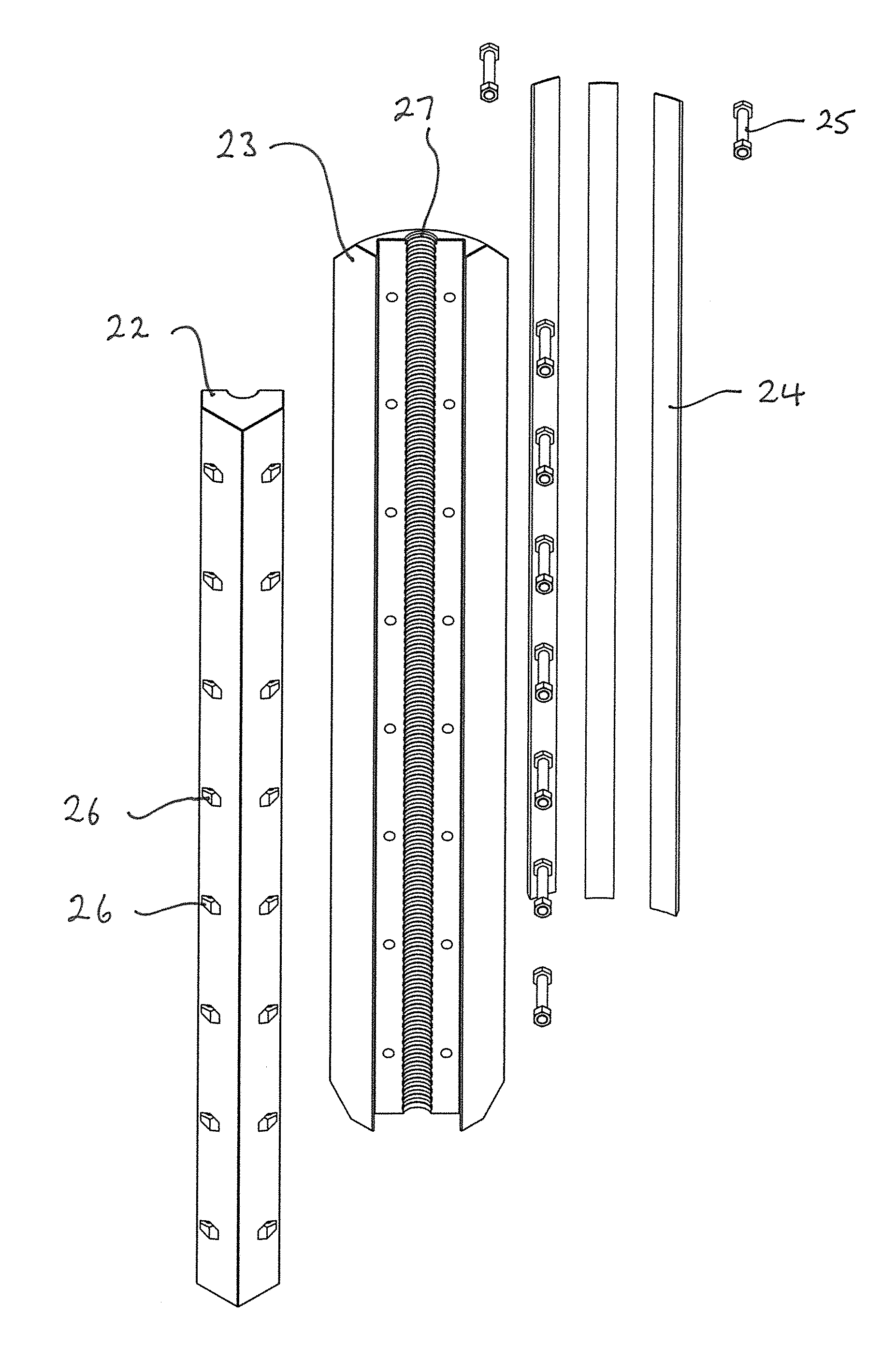
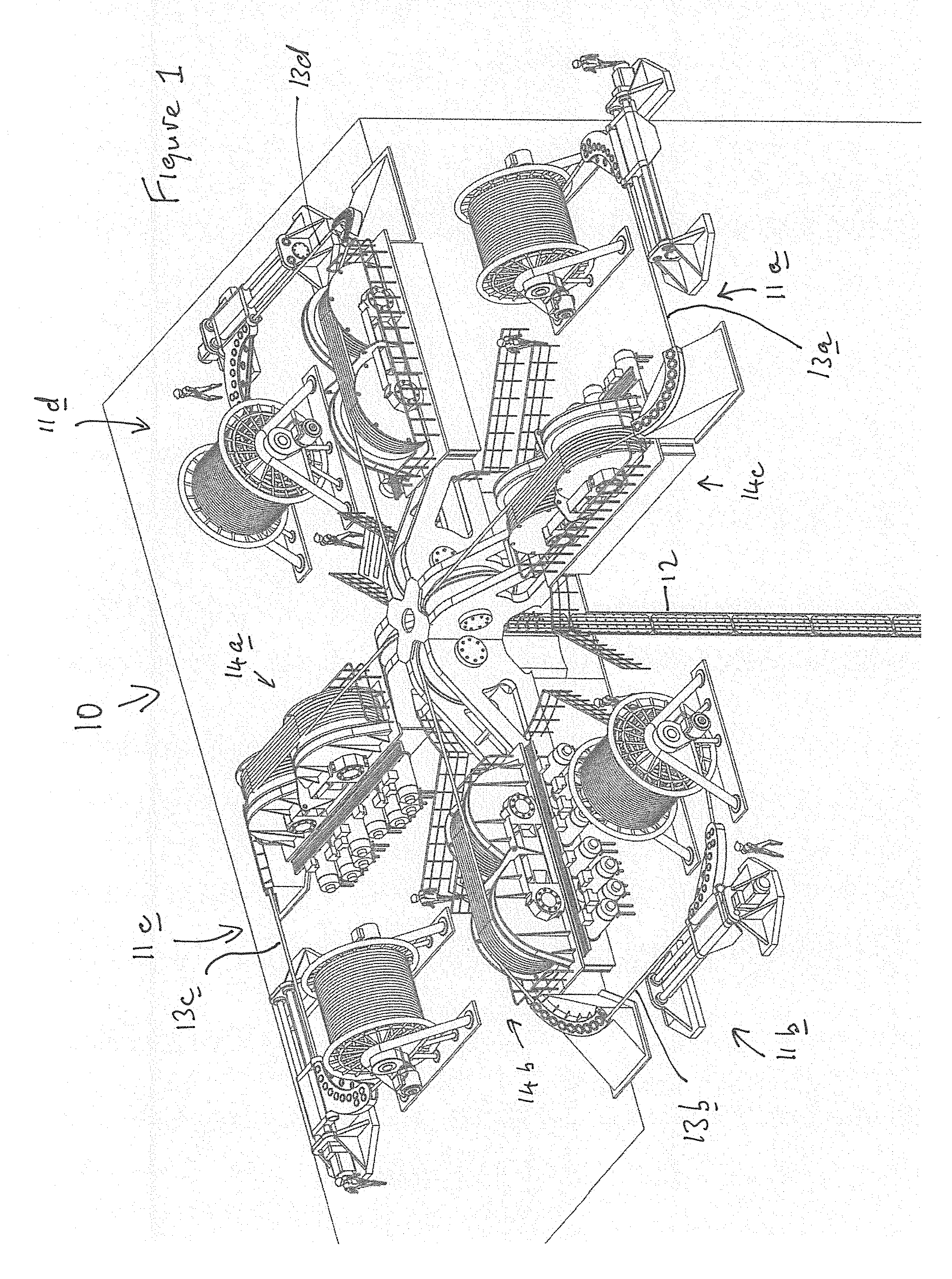
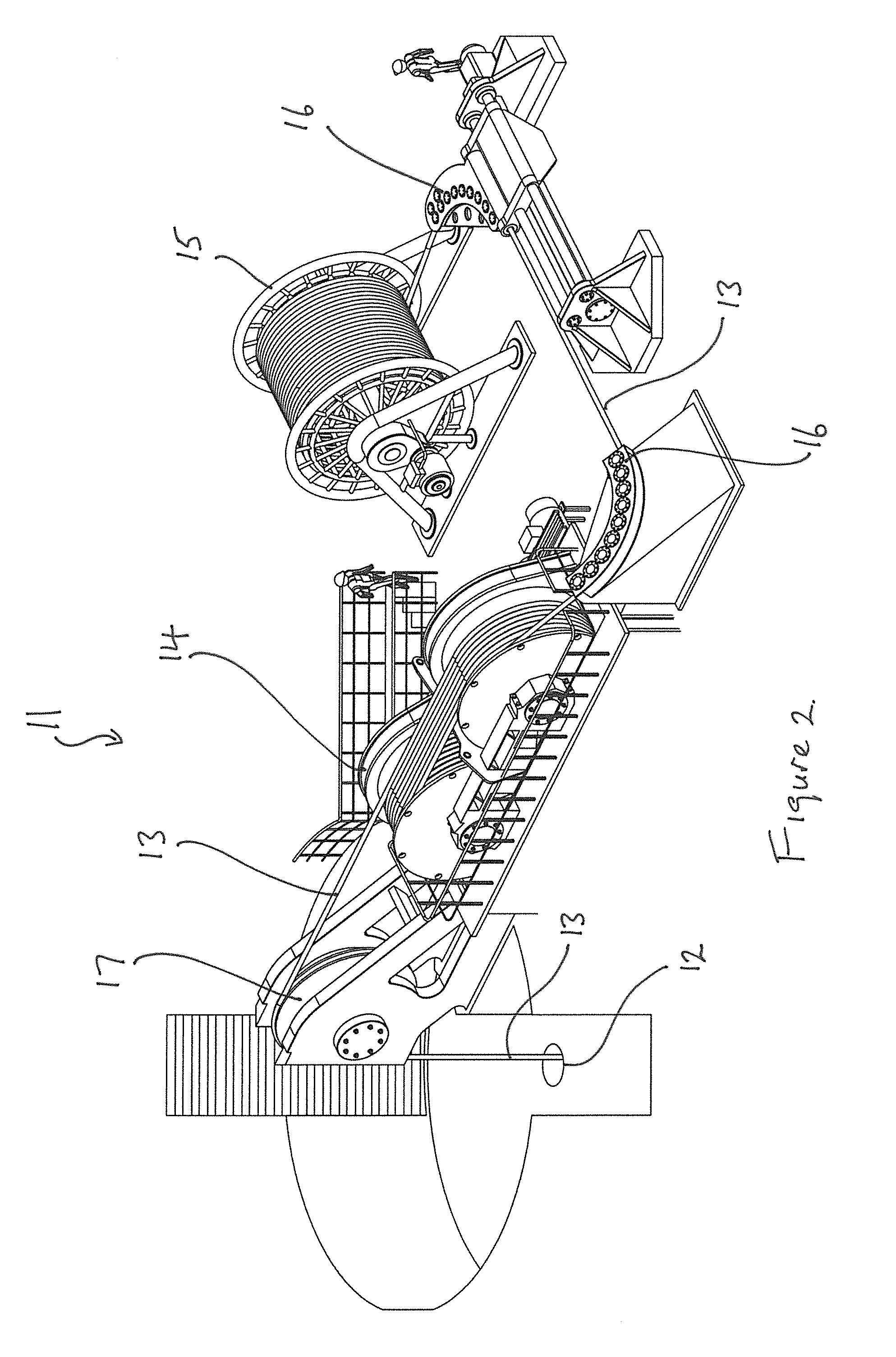
[0069]Referring now to the drawings wherein similar numerals have been used to indicate like parts, there is shown therein an energy storage system generally indicated at 10 according to the invention.

[0070]The energy storage system 10 comprises a plurality of traction winch units 11a, 11b, 11c and 11d disposed around a purpose-build or suitable pre-existing substantially vertical subterranean shaft 12. Each winch unit 11a-11d comprises a steel cable 13a-13d engaged on a fraction type winch system 14 and has a storage reel 15. Spooling guides 16 lead each cable 13a-13d from a respective winch system 14 to an associated storage reel 15. Respective leading sheaves 17 guide the cables 13 into the shaft 12 to support a series of composite mass bodies 20 spaced vertically one above the other in the shaft. A series of motor-generators 18 (FIG. 3) are provided to either drive the traction winches 14 in a forward direction to raise the mass bodies (20) in the shaft (12) to store potential e...


PUM


Abstract

An energy storage system comprises a cable (13) and a mass 20 suspended from the cable (13) in a shaft (12). The cable (13) is attached to a winch 11 by which the mass may be raised in the shaft (12) to store potential energy, and the mass is lowerable in the shaft (12) to release the potential energy. The mass comprises at least two sections clamped together around the cable (13). More particularly, the system comprising a plurality of cables (13) and a plurality of multi-section masses each suspended in the shaft (12) by a respective cable (13), the masses being raised and lowered in synchronism in the shaft (12). The multi-section masses fit together side-by-side in the shaft (12) to form an overall cylindrical mass body, the multi-section masses each forming a quadrant of the cylindrical mass body.

Description

CROSS REFERENCE TO RELATED APPLICATION[0001]The present application relates and claims priority to, and is the United States National Phase application Under 35 U.S.C. 371 of Applicant's PCT Application No. PCT / EP2014 / 053759 filed 26 Feb. 2014 which in turn claims priority to Ireland Application No. S2013 / 0066, filed on 27 Feb. 2013, the entirety of each of which is hereby incorporated by reference.BACKGROUND OF THE INVENTION[0002]1. Technical Field[0003]The present invention relates to a gravitational potential energy storage system capable of storing and regenerating energy by using a mass suspended from a cable.[0004]2. Related Art[0005]From the earliest days of the electric power system, energy storage has been considered an important technology for managing the grid. Today, the changing ways in which electric power is generated and used are making storage even more attractive than before. Energy storage can improve asset utilization, enhance the network reliability, enable more...

Claims


Application Information

Patent Timeline
IPC IPC(8): F03G3/00
CPCF03G3/00Y02E10/72Y02E70/30F03D9/16
Inventor MCGRATH, BRENDAN
Owner OCEAN RENEWABLES
Why Eureka
Try Eureka