Portable bullet trap

a bullet trap and portable technology, applied in the field of portable bullet traps, can solve the problems of difficult transportation of the device from one location to another, and achieve the effect of convenient portability and minimizing the risk of the bullet passing

Inactive Publication Date: 2016-01-07
DURYNSKI ERIC +1
View PDF0 Cites 11 Cited by
  • Summary
  • Abstract
  • Description
  • Claims
  • Application Information

AI Technical Summary

Benefits of technology

[0005]An object of this invention is to provide a bullet trap which is readily portable and which mini

Problems solved by technology

One of the difficulties with known devices is the relatively heavy weight of such

Method used


Image

  • Portable bullet trap
  • Portable bullet trap
  • Portable bullet trap

Examples


Embodiment Construction

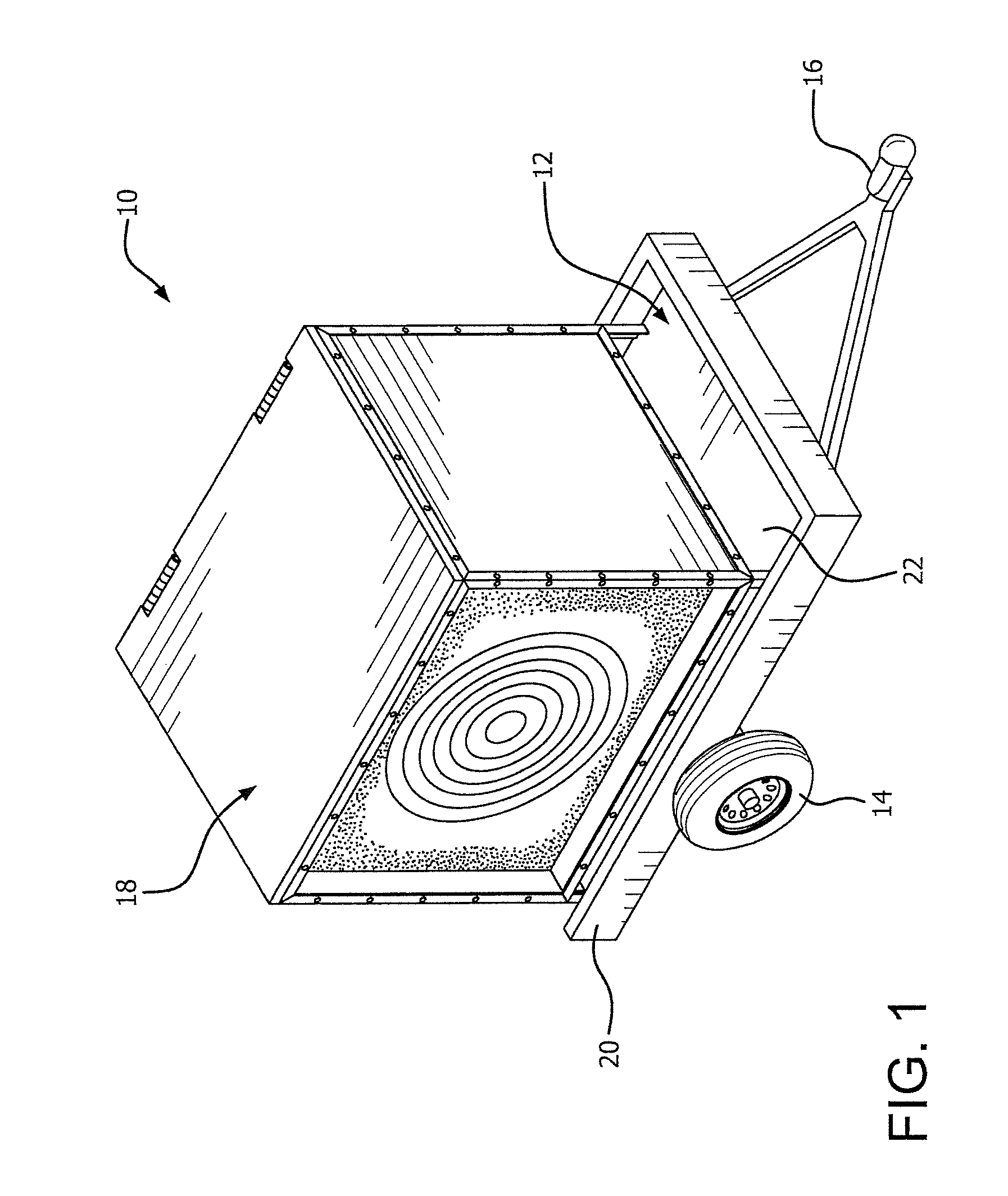
[0012]FIG. 1 illustrates a portable bullet trap 10 in accordance with this invention. As shown therein, bullet trap 10 comprises a support member 12 mounted on wheels 14 so as to be readily movable from one location to another. Preferably the support member 12 is a trailer having its wheels 14 on each side of the trailer and having a front hitch 16.

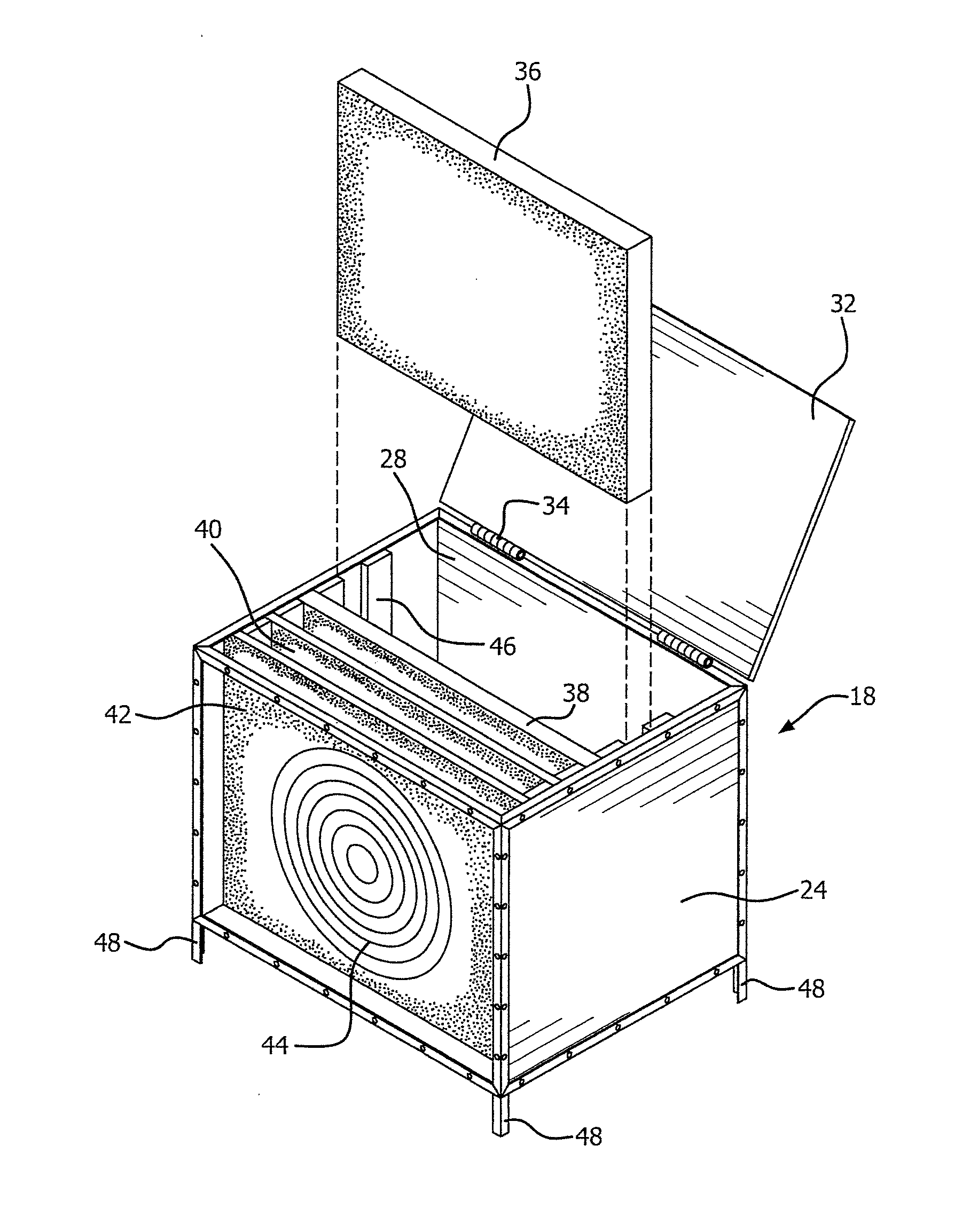
[0013]A bullet trap box 18 is placed on the upper surface 22 of trailer 12 within the upstanding three sided peripheral wall 20. Box 18 could be oriented in any preferred manner on the upper surface 22 of trailer 12. FIG. 1 illustrates the target side or front side of the box located at a side of the trailer. If desired, the front side could be at the rear of the trailer and the back side located near the front of the trailer toward the hitch 16.

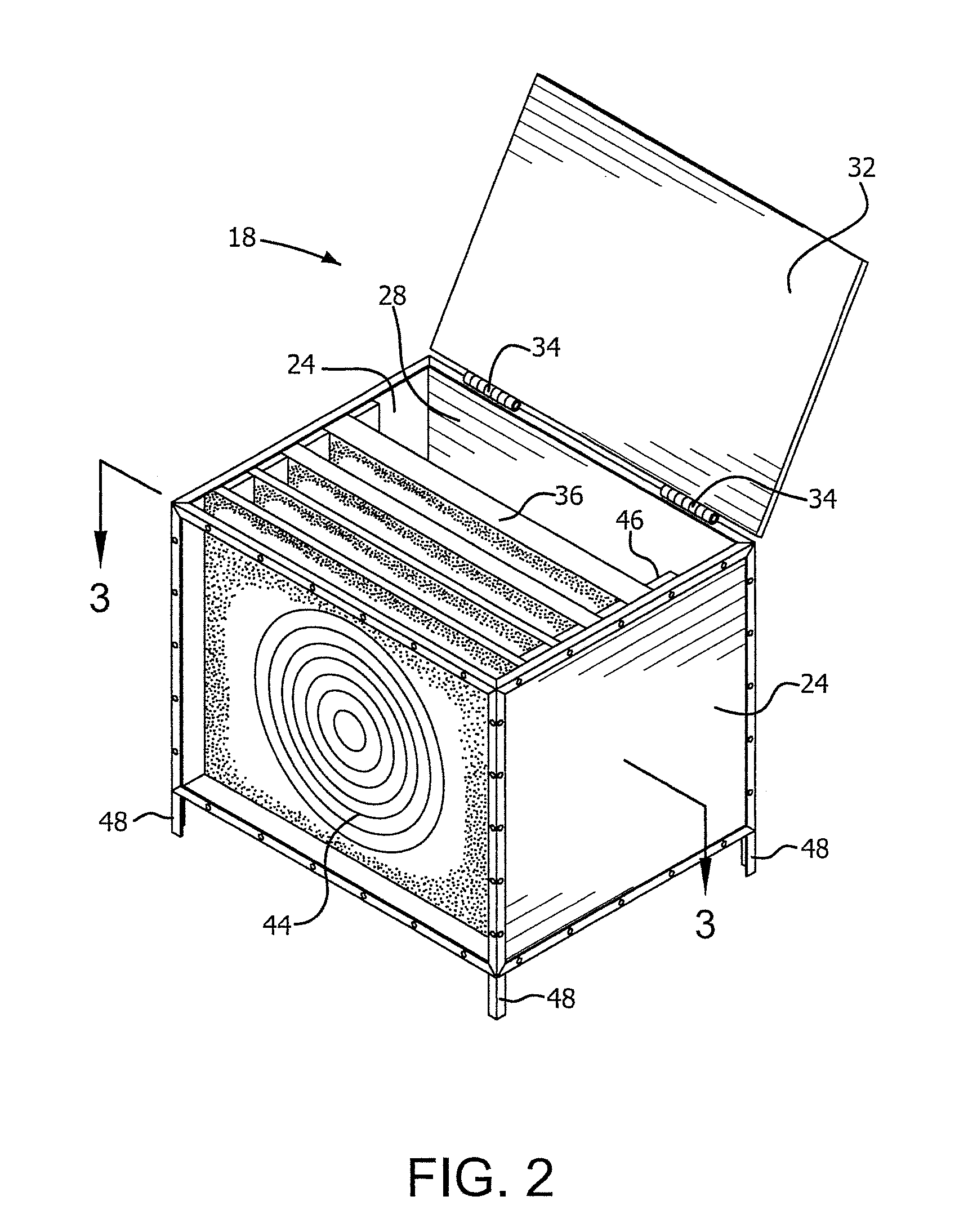
[0014]FIGS. 2-3 illustrate the details of bullet trap box 18. As illustrated, the bullet trap box 18 comprises a pair of spaced side walls 24,24 interconnected by a back wall 28 and an open front ...


PUM


Abstract

A portable bullet trap includes a trailer having a hitch. A bullet trap box is removably placed on the trailer. The bullet trap box is formed by a pair of spaced side walls interconnected by a back wall and having a front face. A bottom wall is below the side walls and the front face and back wall. A top wall is hinged to the back wall and is movable from a closed position covering the interior of the box and to an open position exposing the interior of the box. Baffles made from energy absorbing material, such as rubber, are detachably mounted within the box.

Description

CROSS-REFERENCE TO RELATED APPLICATION[0001]This application is based on provisional application Ser. No. 61 / 844,033, filed Jul. 9, 2013, all of the details of which are incorporated herein by reference thereto.BACKGROUND OF INVENTION[0002]One of the concerns in target shooting is that a bullet might hit the target and then penetrate and continue its motion until it strikes an unintended object or person. Some attempts have been made to provide some structure for trapping a bullet. U.S. Pat. No. 7,475,880, for example, discloses a ballistic target which includes a bullet stopping plate with a bullet trapping panel. U.S. Published Application US2012 / 0038110 discloses a bullet decelerating medium and bullet trapping system which includes a support frame and flowable material disposed on an upper surface of the support frame. The support frame has an upper surface configured to support associated material. The flowable material includes a plurality of sheets of substantially rectangula...

Claims


Application Information

Patent Timeline
IPC IPC(8): F41J13/00
CPCF41J13/00F41J13/02
Inventor DURYNSKI, ERICTOTO, ALEXANDER R.
Owner DURYNSKI ERIC
Why Eureka
Try Eureka