Eye-wearable device user interface and augmented reality method

a wearable device and user interface technology, applied in the field of user interfaces for headmounted displays, can solve the problems of obstructing real, virtual or augmented data training, reducing the usefulness of augmented data, and conspicuousness, so as to achieve the effect of reducing user training

Active Publication Date: 2016-01-07
SNAP INC
View PDF20 Cites 60 Cited by
  • Summary
  • Abstract
  • Description
  • Claims
  • Application Information

AI Technical Summary

Benefits of technology

[0005]In one embodiment, the invention may be a software controlled user interface and method for an eye-wearable device, designed to accommodate angular accuracy versus time averaging tradeoffs for either eye gaze direction or fingertip detection. The method is simple, intuitive, and can scale between displaying a small to large number of different target symbols at any given time, yet still transmit a large array of different symbols to outside devices with minimal user training At least part of the method may be implemented by way of a virtual window onto the surface of a virtual cylinder, with sensitive...

Problems solved by technology

If this functionality is not addressed by the user interface, the augmented data becomes less useful, and social friction and/or lost business opportunities can result.
For example, an augmented image that the device user cannot then quickly and easily select for an additional computing, such as sharing with contacts, is less useful than one that also affords additional actionable options.
However the act of using a cell phone or other handheld mobile device to perform a computing command in response to any real, virtual, or augmented data can be o...

Method used


Image

  • Eye-wearable device user interface and augmented reality method
  • Eye-wearable device user interface and augmented reality method
  • Eye-wearable device user interface and augmented reality method

Examples


Embodiment Construction

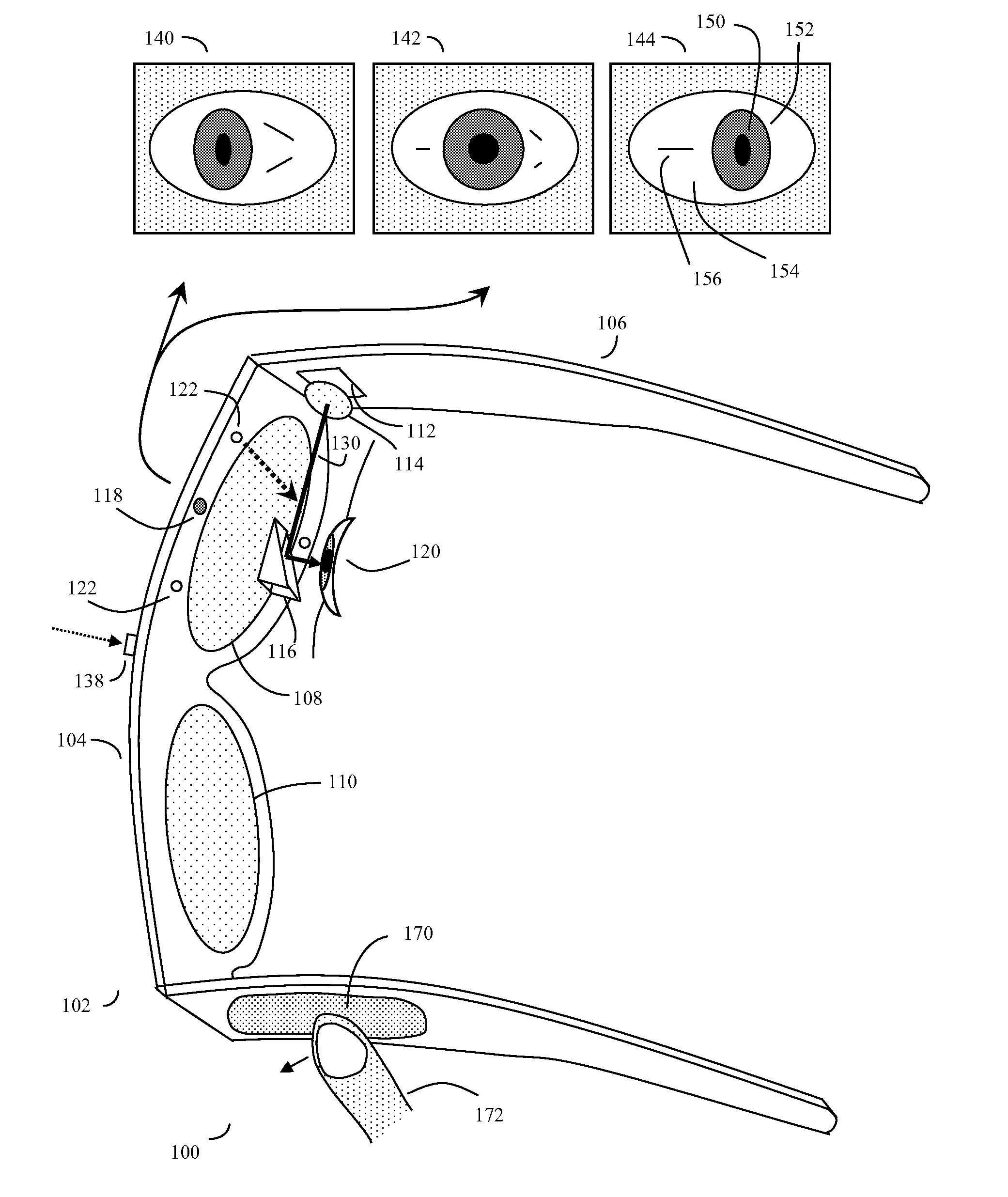
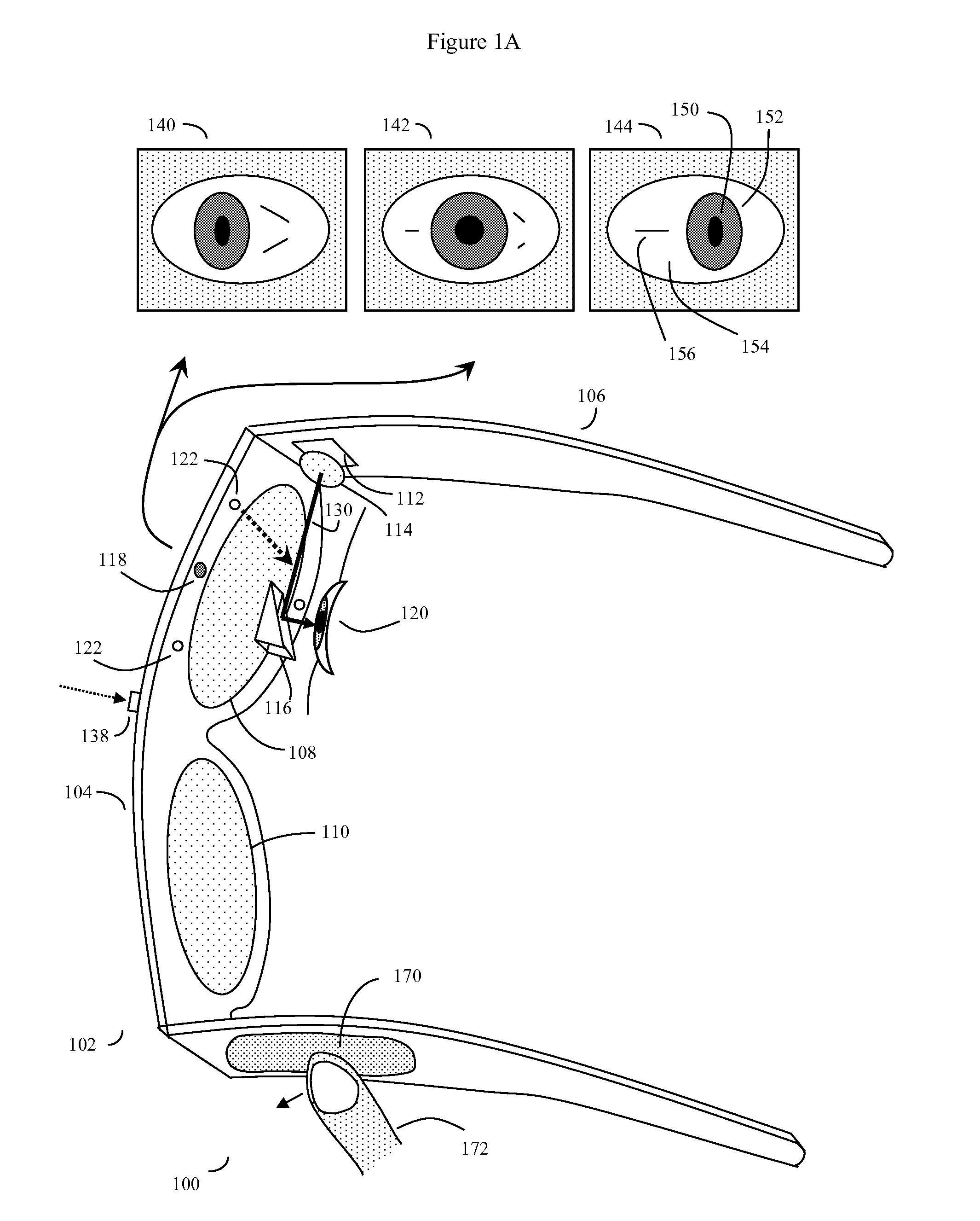
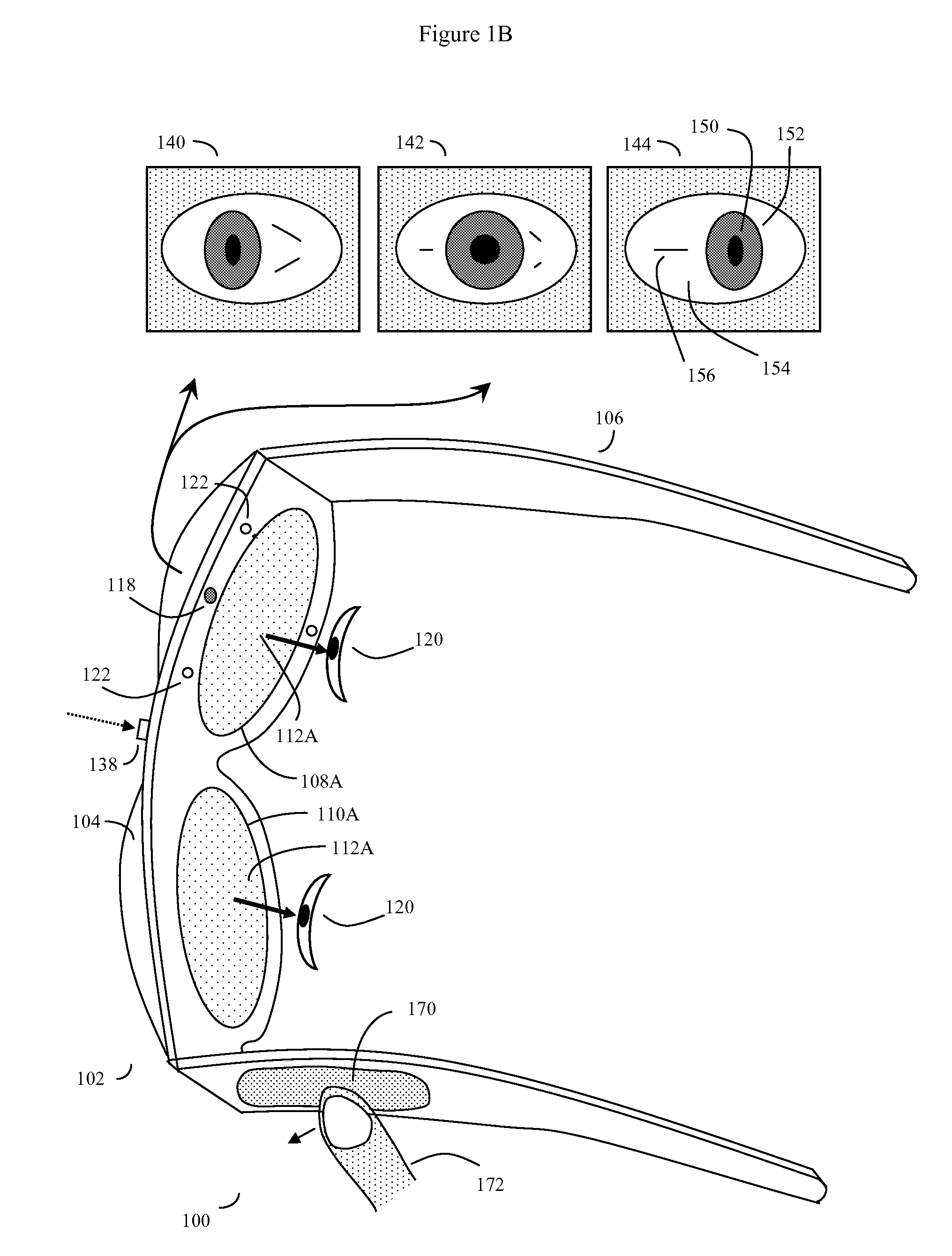
[0025]In previous parent applications, exemplified by parent U.S. patent applications Ser. Nos. 14 / 066,654, 13 / 117,146, 13 / 034,182, and 12 / 842,315, the contents of which are incorporated herein by reference, methods of controlling various eye wearable devices were proposed. To generalize, the challenge is to solve a complex problem of devising a simple to use but flexible user interface to control these and other types of devices. In addition to the previously discussed telecommunications options, Many other eye-wearable devices have been proposed that provide virtual or augmented data or images that automatically present to the user based on GPS, altimeter, accelerometer, outward-pointed camera, or other sensors onboard the device.

[0026]Here the problems in making the virtual or augmented data or images actionable to the user should be appreciated. In order to provide optimal functionality, any actionable virtual or augmented content automatically transmitted to the user's device m...


PUM


Abstract

A software controlled user interface and method for a head-mountable device equipped with at least one display or connectivity to at least one touch pad. The method can scale between displaying a small to large number of different eye gaze target symbols at any given time, yet still transmit a large array of different symbols to outside devices. At least part of the method may be implemented by way of a virtual window onto the surface of a virtual cylinder, with touchpad or eye gaze sensitive symbols that can be rotated by touchpad touch or eye gaze thus bringing various groups of symbols into view, and then selected. Specific examples of use of this interface and method on a head-mountable device are disclosed, along with various operation examples including transmitting data including text, functionality in virtual or augmented reality, control of robotic devices and control of remote vehicles.

Description

BACKGROUND OF THE INVENTION[0001]This application is a continuation in part of U.S. patent application Ser. No. 14 / 716,510, “EYE-WEARABLE DEVICE USER INTERFACE AND METHOD”, filed May 19, 2015; application Ser. No. 14 / 716,510 in turn is a continuation in part of U.S. patent application Ser. No. 14 / 066,654, “EYE GAZE USER INTERFACE AND CALIBRATION METHOD”, filed Oct. 29, 2013; Ser. No. 14 / 066,654 was a continuation in part of U.S. patent application Ser. No. 13 / 117,146, “EYE GAZE USER INTERFACE AND METHOD” filed May 27, 2011, now U.S. Pat. No. 8,593,375; Ser. No. 13 / 117,146 in turn was a continuation in part of U.S. patent application Ser. No. 13 / 034,182 filed Feb. 24, 2011, now U.S. Pat. No. 8,531,394; Ser. No. 13 / 117,146 was also a continuation in part of U.S. patent application Ser. No. “12 / 842,315, “Unitized, Vision-Controlled, Wireless Eyeglass Transceiver”, filed Jul. 23, 2010; now U.S. Pat. No. 8,531,355; the contents of all of these applications are incorporated herein by refe...

Claims


Application Information

Patent Timeline
IPC IPC(8): G06F3/01G02B27/00G02B27/01G06F3/041G06F3/0481G06F3/0484
CPCG06F3/013G02B27/0172G02B27/0179G02B27/0093G06F3/016G06F3/017G06F2203/04808G06F3/04817G06F3/04845G02B2027/0178G02B2027/0187G06F2203/04104G06F3/0412G02B27/017G02B2027/0138G02B2027/014G09G2354/00G02B2027/0141
Inventor MALTZ, GREGORY, A.
Owner SNAP INC
Why Eureka
Try Eureka