User Interface For An Aircraft

a user interface and aircraft technology, applied in the field of aircraft control systems and instrument panels, can solve the problems of limited flexibility and customizability of instrument panels, limited effective area of instrument panels available for display of information, and fixed locations of instruments. , to achieve the effect of modifying the state of the aircra

Active Publication Date: 2016-01-07
TEXTRON INNOVATIONS
View PDF27 Cites 46 Cited by
  • Summary
  • Abstract
  • Description
  • Claims
  • Application Information

AI Technical Summary

Benefits of technology

[0015]To allow for customization of the instrument panel, some embodiments allow a user to drag a synoptic user interface panel to a desired location on the touch screen instrument panel. In some embodiments, the user can pin the user interface panel in a desire location by actuating an icon displayed in the synoptic user interface panel thereby preventing the synoptic user interface panel from being moved from the desired location. Then the user may touch the touch screen instrument panel in the area depicting the synoptic user interface panel to manipulate the information provided on the synoptic user interface panel. When the user is finished manipulating the information in the user interface panel, the user may actuate the icon to unpin the at least one user interface panel allowing the panel to be moved from the desired location. In some embodiments of the user interface, one user interface panel may overlay a second user interface panel.
[0017]In some embodiments, the display element is an icon associated with the depiction of all or a portion of an aircraft. In some of those embodiments, receiving control input comprises sensing a touch input on the icon. In some the embodiments, the icon is associated with an anti-icing system, and actuating the icon modifies the state of the aircraft by turning the anti-icing system on or off. In other embodiments, the icon is associated with the temperature of a portion of the aircraft, and actuating the icon modifies the state of the aircraft by increasing or decreasing the temperature settings for the portion of the aircraft.
[0018]In some embodiments, the icon is associated with the position of a control surface for the aircraft, and actuating the icon modifies the state of the aircraft by repositioning the control surface.

Problems solved by technology

As a result of their single purpose and physical arrangement, the instrument panel has limited flexibility and customizability.
The instruments are in fixed locations and are limited in what information they can display or input they can receive from the user.
This reduces the effective area of the instrument panel available for the display of information.

Method used


Image

  • User Interface For An Aircraft
  • User Interface For An Aircraft
  • User Interface For An Aircraft

Examples


Embodiment Construction

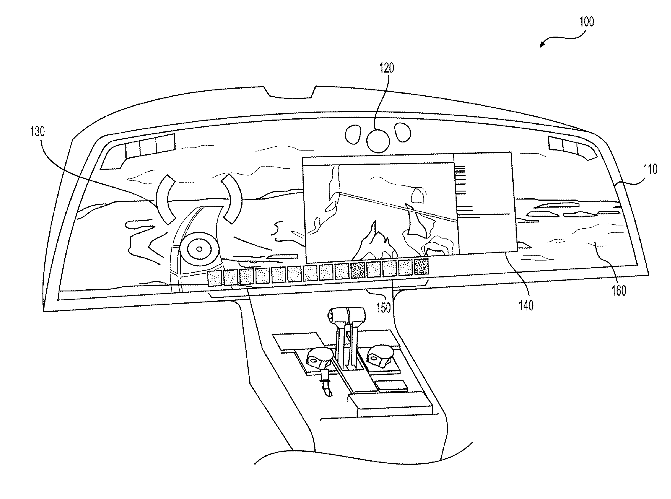
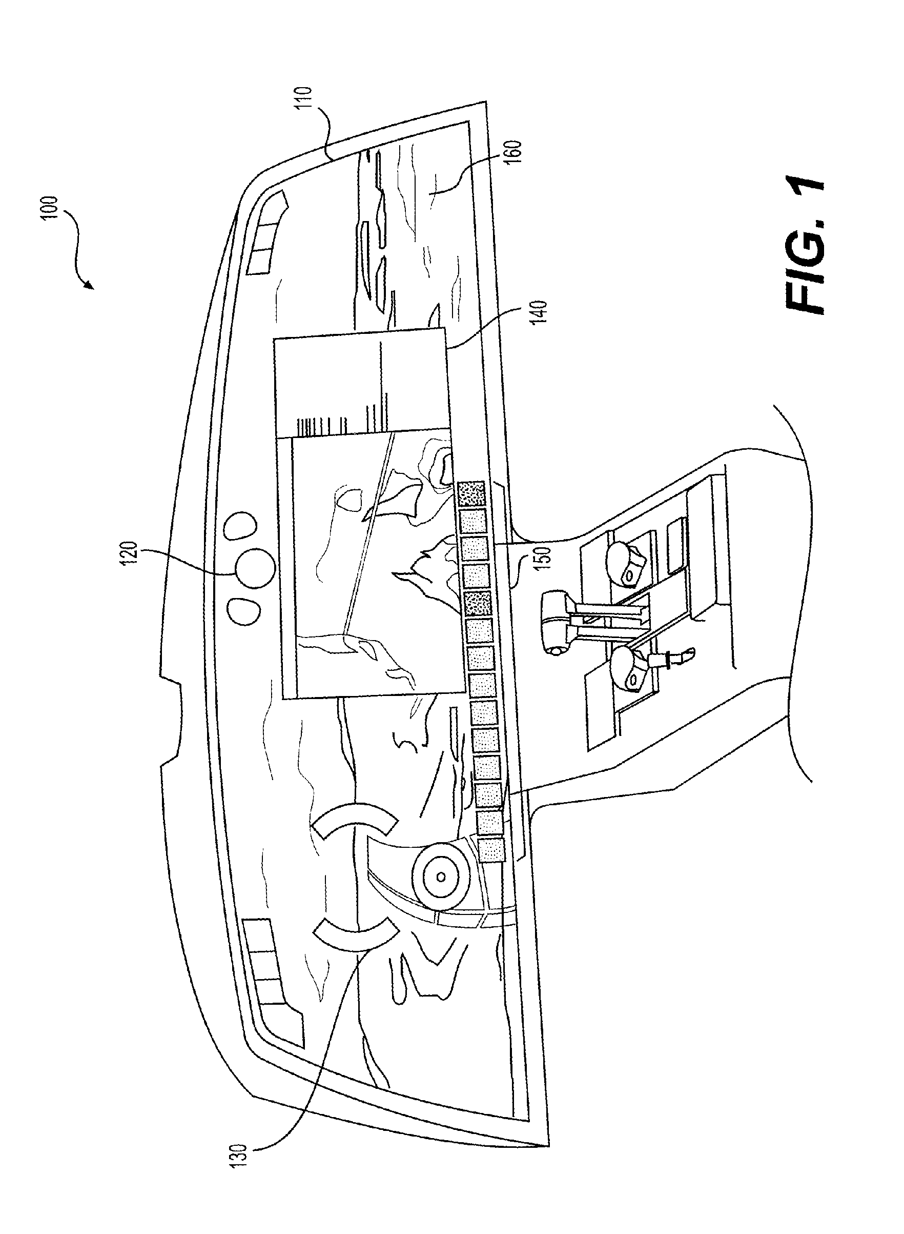
[0035]Referring to FIG. 1, a representation 100 of a touch-screen instrument panel (TSIP) is illustrated. The TSIP replaces the plurality of instruments, dials, gauges, and screens typically utilized on the console of an aircraft. The TSIP is configured for at least a touch screen implementation. In some embodiments, the TSIP may span the width of a cockpit of an aircraft. As illustrated in FIG. 1, the TSIP is the width of the cockpit and may be accessed by both a pilot, co-pilot, and the like.

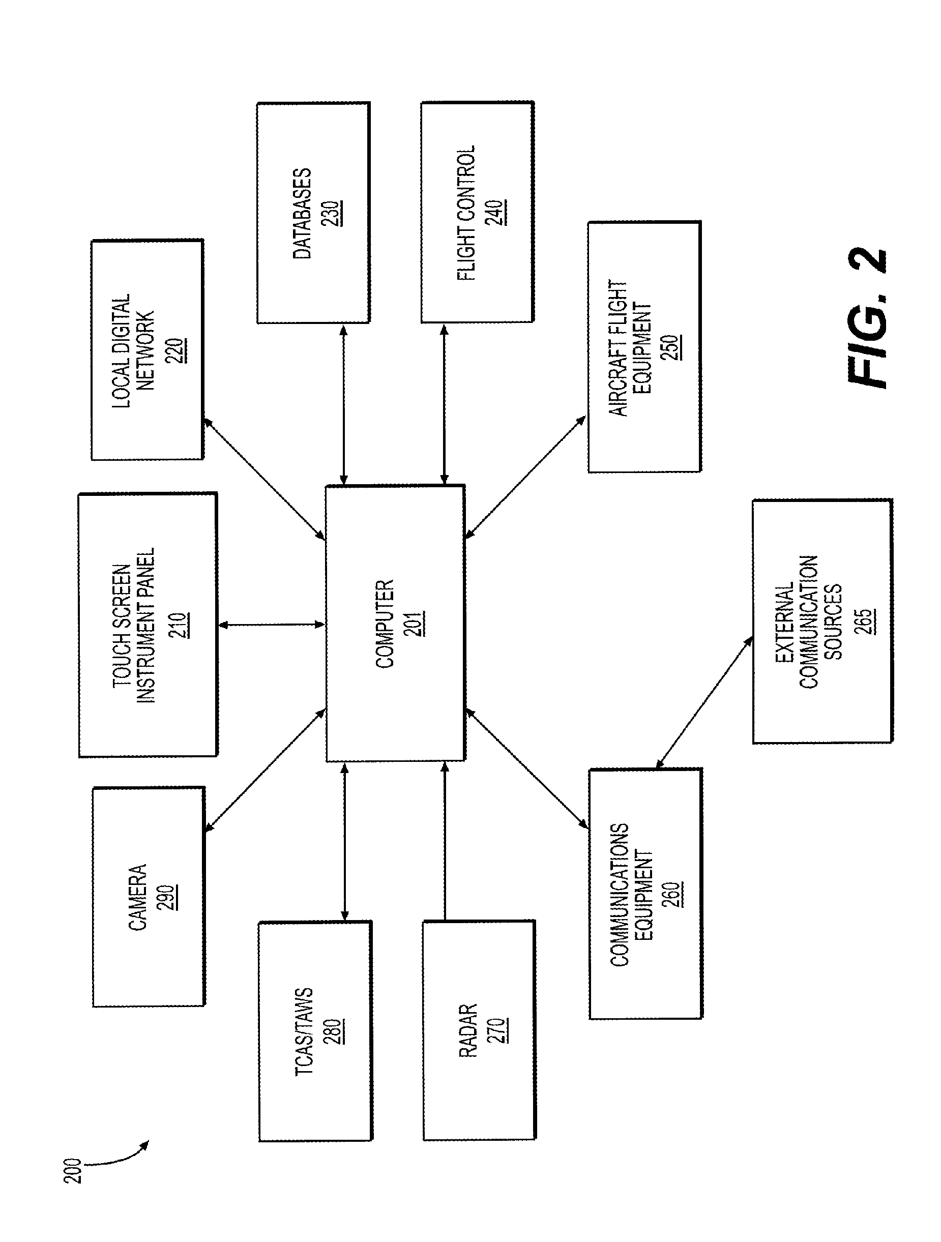
[0036]The TSIP is a digital information panel and may include a plurality of digital layers. The digital layers may overlay one another to create multiple views. For instance, and as will be described in further detail below, one layer may be a real-time view while another layer may be a three-dimensional representation of, for example, weather while another layer may include flight instruments and may not be obstructed with any other layers or representations. A processor, similar to that onb...


PUM


Abstract

Systems and methods are described for controlling an aircraft. The systems and methods utilize a touch screen instrument panel to display information to pilots or other users, and to receive input from the user for controlling the aircraft and its components. The systems and methods include synoptic user interface panels that provide graphical or symbolic representations of the aircraft, its components, and subsystems, and display information regarding their configuration, condition, and status. The users may interact with the synoptic user interface panels through the touch screen instrument panel to control the various components of the aircraft.

Description

CROSS REFERENCE TO RELATED APPLICATIONS[0001]This application is a continuation-in-part of U.S. patent application Ser. No. 14 / 642,256, entitled “Touch Screen Instrument Panel”, filed Mar. 9, 2015, which claims the benefit of each of U.S. Provisional Application No. 61 / 951,145, entitled “3D Weather”, U.S. Provisional Application No. 61 / 951,189, entitled “HD Camera”, U.S. Provisional Application No. 61 / 951,260, entitled “Adjustable Synthetic Vision System”, U.S. Provisional Application No. 61 / 951,231, entitled “Skytrak Navigational Aid”, U.S. Provisional Application No. 61 / 951,240, entitled “Smart Airport Application”, U.S. Provisional Application No. 61 / 951,243, entitled “Smart Traffic Application”, U.S. Provisional Application No. 61 / 951,157, entitled “Chart Synoptic Window”, U.S. Provisional Application No. 61 / 951,168 entitled “Flight Planning Synoptic Window”, U.S. Provisional Application No. 61 / 951,201 entitled “Intelligent Radio Frequency Identifiers”, U.S. Provisional Applicat...

Claims


Application Information

Patent Timeline
Patent Type & Authority Applications(United States)
IPC IPC(8): G06F3/041G06F3/0481
CPCG06F3/04817G06F3/0416B64D43/00G01C23/00G08G5/0021G08G5/0091G06F3/0488G06F3/0484
Inventor KNEUPER, JEREMY JOSEPHDECKER, JASON MICHAELSTANFIELD, ISAAC WAYNE
Owner TEXTRON INNOVATIONS
Why Eureka
Try Eureka