Patient interface with venting

a patient interface and gas venting technology, applied in the field of patient interfaces for respiratory therapy, can solve problems such as disturbance for patients and/or their bed partners, and patients' health hazards, and achieve the effect of preventing occlusion

Active Publication Date: 2016-01-14
FISHER & PAYKEL HEALTHCARE LTD
View PDF10 Cites 101 Cited by
  • Summary
  • Abstract
  • Description
  • Claims
  • Application Information

AI Technical Summary

Benefits of technology

[0027]In other configurations, the plurality of passages can be formed on the male portion of the coupling. The plurality of passages that are f

Problems solved by technology

As the patient breathes, carbon dioxide gases can progressively accumulate in the delivery system, which if left over a period o

Method used


Image

  • Patient interface with venting
  • Patient interface with venting
  • Patient interface with venting

Examples


Embodiment Construction

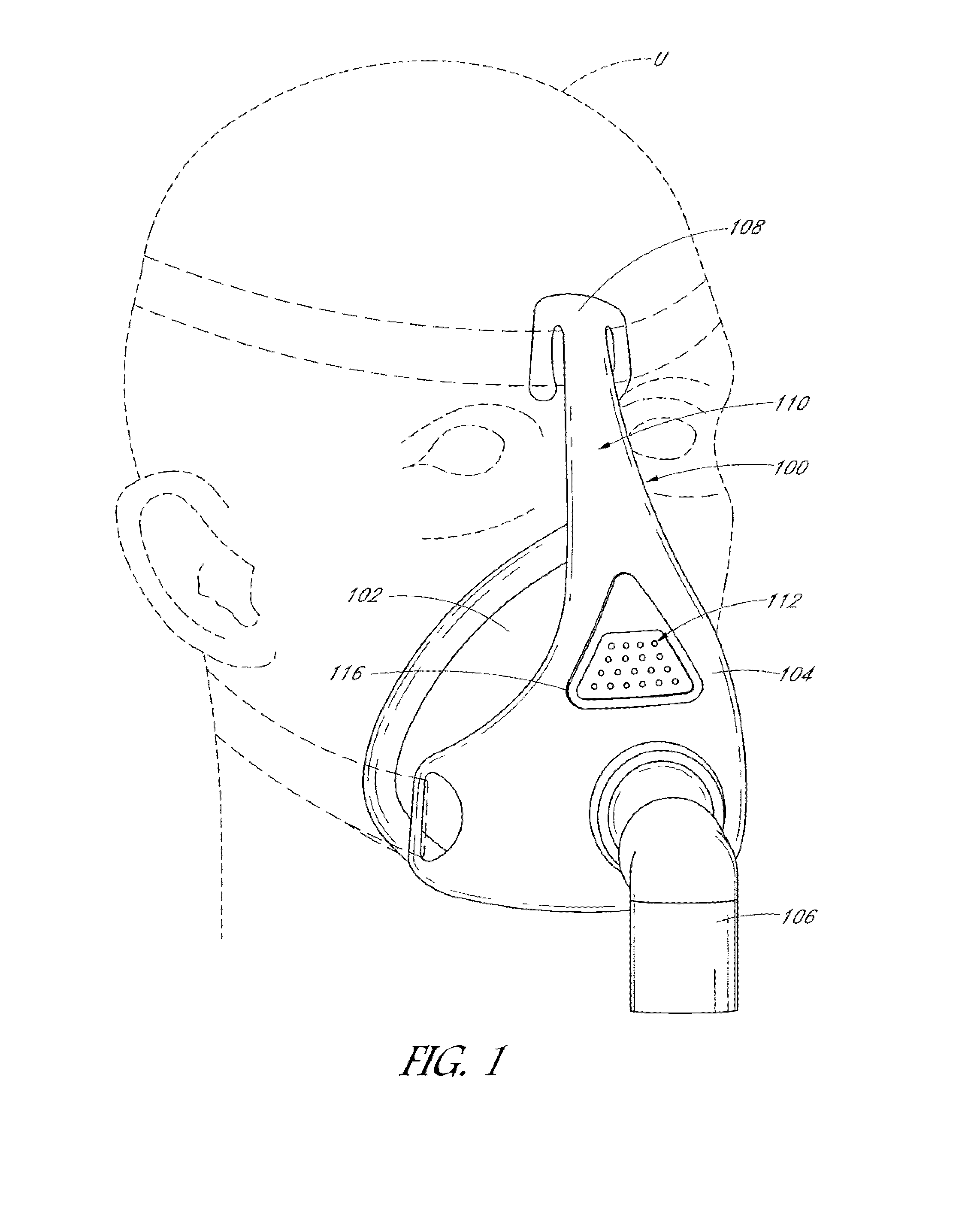
[0072]With reference initially to FIG. 1, an embodiment of an interface 100 is illustrated on a user U. The interface 100 can be used in the field of respiratory therapy. In some embodiments, the interface 100 has particular utility with forms of positive pressure respiratory therapy. For example, the interface 100 can be used for administering continuous positive airway pressure (“CPAP”) treatments, variable positive airway pressure (“VPAP”) treatments and / or bi-level positive airway pressure (“BiPAP”) treatments. The interface can be compatible with one or more different types of suitable CPAP systems.

[0073]The interface 100 can comprise any of a plurality of different types of suitable mask configurations. For example, certain features, aspects and advantages of the present invention can be utilized with nasal masks, full face masks, oronasal masks or any other positive pressure mask. Although the illustrated mask is a full face mask, the scope of the present disclosure should no...


PUM


Abstract

Interfaces for positive pressure therapy having various vent designs are disclosed herein. The interfaces include a bias flow vent with design geometries that help reduce and/or minimize draft and noise levels of the fluids exiting the vents. Some of the vent designs include particular vent hole geometries, plenum spaces, diffusers and fibrous media.

Description

INCORPORATION BY REFERENCE TO ANY PRIORITY APPLICATIONS[0001]Any and all applications for which a foreign or domestic priority claim is identified in the Application Data Sheet as filed with the present application are hereby incorporated by reference and made a part of the present disclosure.BACKGROUND OF THE INVENTION[0002]1. Field of the Invention[0003]The present invention generally relates to patient interfaces for respiratory therapy. More particularly, certain aspects of the present disclosure relate to various systems and methods for venting gases from patient interfaces.[0004]2. Description of the Related Art[0005]The treatment of obstructive sleep apnea (OSA) by continuous positive airway pressure (CPAP) flow generator systems involves the continuous delivery of pressurized gases to the airways of a human via a conduit and an interface (e.g., a mask). Typically the interface creates at least a substantial seal on or around the nose and / or the mouth. As the patient breathes...

Claims


Application Information

Patent Timeline
IPC IPC(8): A61M16/00A61M16/06
CPCA61M16/0683A61M16/0003A61M16/06A61M16/208A61M2205/42A61M16/0825A61M16/0616A61M16/0633A61M16/0866A61M2202/0225A61M2202/0085A61M16/1065A61M2205/75
Inventor HUDDART, BRETT JOHNGANE, RONALDGORDON, CALLUM ROSSTHOMPSON, MARK ANDREWRICHARDSON, THOMAS MARK
Owner FISHER & PAYKEL HEALTHCARE LTD
Why Eureka
Try Eureka