Earthquake prediction device

a prediction device and earthquake technology, applied in measurement devices, scientific instruments, instruments, etc., can solve the problems of difficult replacement, mmi scale is hardly suited to instrumental measurement, and documents 1 and 2 cannot be used abroad, so as to reduce accidents and be easy to understand globally.

Inactive Publication Date: 2016-01-14
CENTRAL JAPAN RAILWAY COMPANY
View PDF2 Cites 5 Cited by
  • Summary
  • Abstract
  • Description
  • Claims
  • Application Information

AI Technical Summary

Benefits of technology

[0034]Accordingly, the earthquake prediction device of the present invention enables reduction of accidents, such as a rollover of a train due to collapse of embankments or the like, by stopping the train early using an automatic train stop device at occurrence of an earthquake.
[0035]Furthermore, in the earthquake prediction device of the present invention, prediction of an earthquake that is easy to understand globally is possible because the MMI scale is used as the ground motion index.

Problems solved by technology

However, the Modified Mercalli Intensity (MMI) scale is internationally used as the ground motion index, and thus, the devices set forth in the above-described Patent Documents 1 and 2 cannot be used abroad as they are.
However, the MMI scale is a ground motion index determined on the basis of human bodily sensation or investigations of the damage situation after the earthquake, and thus, the MMI scale is hardly suited to instrumental measurement, and such replacement is not easy.

Method used


Image

  • Earthquake prediction device
  • Earthquake prediction device
  • Earthquake prediction device

Examples


first embodiment

[0063]1. Earthquake Prediction Device 1

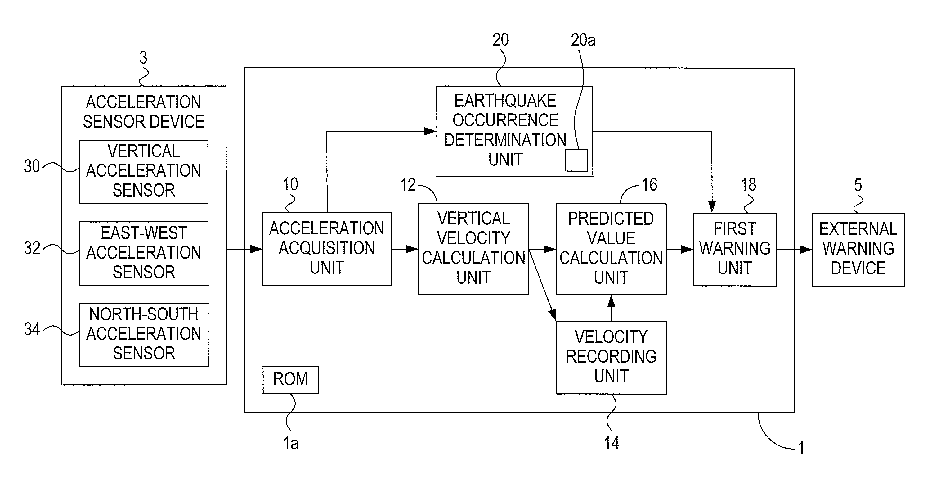
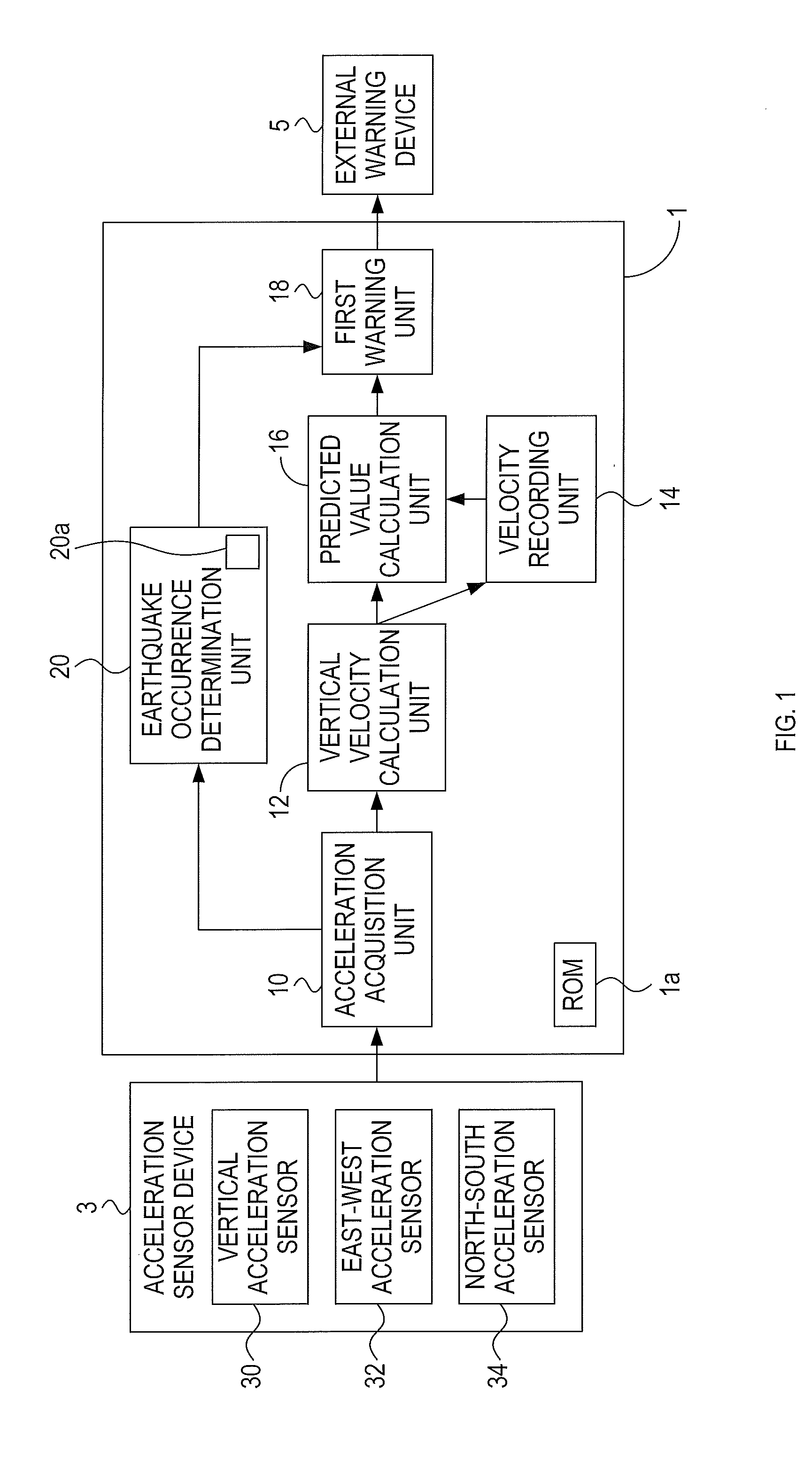
[0064]An earthquake prediction device 1 of a first embodiment will be explained with reference to FIG. 1. It is to be noted that the first embodiment will be referred to as the present embodiment in the sections below in which the first embodiment is explained.

[0065]The earthquake prediction device 1 of the present embodiment is a computer device including a CPU, a ROM 1a, a RAM, and so on. The CPU and the RAM are not illustrated in FIG. 1.

[0066]Connected to the earthquake prediction device 1 are an acceleration sensor device 3 and an external warning device 5.

[0067]Among these, the acceleration sensor device 3 comprises three acceleration sensors (a vertical acceleration sensor 30, an east-west acceleration sensor 32, and a north-south acceleration sensor 34) that detect a ground motion as acceleration components in three directions (vertical, east-west, and north-south) orthogonal to each other.

[0068]In the present embodiment, observation poi...

second embodiment

[0148]Next, a second embodiment of the present invention will be explained.

[0149]In the present embodiment, only differences from the first embodiment will be explained. It is to be noted that the second embodiment is referred to as the present embodiment in the sections below in which the second embodiment is explained.

[0150]1. Earthquake Prediction Device 1

[0151]As shown in FIG. 7, the earthquake prediction device 1 of the present embodiment is different from the earthquake prediction device 1 of the first embodiment in that an adjustment factor setting unit 22 is provided.

[0152]In addition, the present embodiment is different from the first embodiment in that an adjustment value γv is added to the prediction formula for calculation of the predicted value (MMIvp) to be used by the predicted value calculation unit 16.

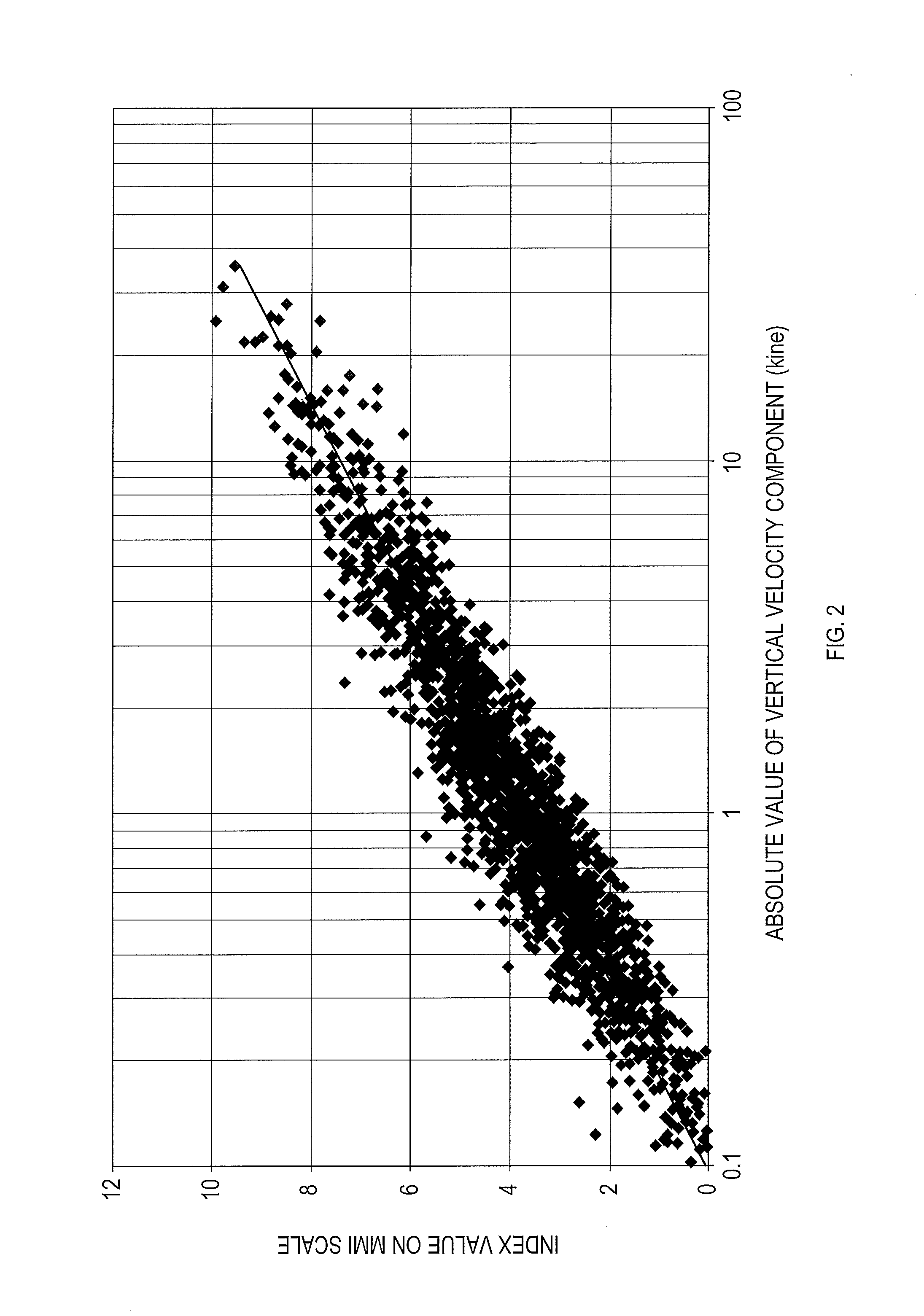
[0153]The prediction formula: MMIvp=αvlog10(Vumax)+βv+γv

[0154]In the present embodiment, γv can be adjusted between −1 and 1. As the adjustment factor setting unit 22,...


PUM


Abstract

An earthquake prediction device comprises a predicted value calculation unit that calculates, from a prediction formula, a predicted value (MMIvp) indicating a predicted intensity of a ground motion on the Modified Mercalli Intensity scale, using a maximum velocity value (Vumax), which is the largest among absolute values of velocity component calculated by a vertical velocity calculation unit, after a sensor starts detecting the ground motion caused by an earthquake. The prediction formula is: MMIvp=αvlog10(Vumax)+βv.

Description

TECHNICAL FIELD[0001]The present invention relates to an earthquake prediction device that predicts an intensity of earthquake shaking at the time of initial tremor of the ground motion, using the Modified Mercalli Intensity scale as a ground motion index indicating the intensity of earthquake shaking.BACKGROUND ART[0002]Presently, a device is known that measures the intensity of earthquake shaking in real time (Patent Document 1).[0003]This device detects acceleration components of the ground motion in three directions (vertical, east-west, and north-south), calculates an acceleration by vector-synthesizing these acceleration components, and calculates an index value indicating the intensity of earthquake shaking from this acceleration, to thereby measure the intensity of earthquake shaking in real time.[0004]In addition, presently, a device is also known that predicts the intensity of earthquake shaking at the time of initial tremor of the ground motion (Patent Document 2).[0005]A...

Claims


Application Information

Patent Timeline
Patent Type & Authority Applications(United States)
IPC IPC(8): G01V1/00G01V1/30
CPCG01V1/303G01V1/008
Inventor TAYA, SHUICHI
Owner CENTRAL JAPAN RAILWAY COMPANY
Why Eureka
Try Eureka