Three-dimensional image output device and background image generation device

Active Publication Date: 2016-01-14
GEO TECHN LAB
View PDF6 Cites 10 Cited by
  • Summary
  • Abstract
  • Description
  • Claims
  • Application Information

AI Technical Summary

Benefits of technology

[0020]This blurs the boundary between the background image and the three-dimensional object image transmitted through the transparent portion and reduces the unnaturalness in the area where the three-dimensional object image is covered with the opaque portion. This also provides a visual effect of blurring the object

Problems solved by technology

Such display, however, needs to provide both a three-dimensional model for the flat ground surface and a three-dimensional model for the spherical ground surface or undesirably increases the processing load of operations to express the horizon by a curved line.
The three-dimensional map may accordingl

Method used


Image

  • Three-dimensional image output device and background image generation device
  • Three-dimensional image output device and background image generation device
  • Three-dimensional image output device and background image generation device

Examples


Example

A. First Embodiment

A1. Three-Dimensional Map Display System

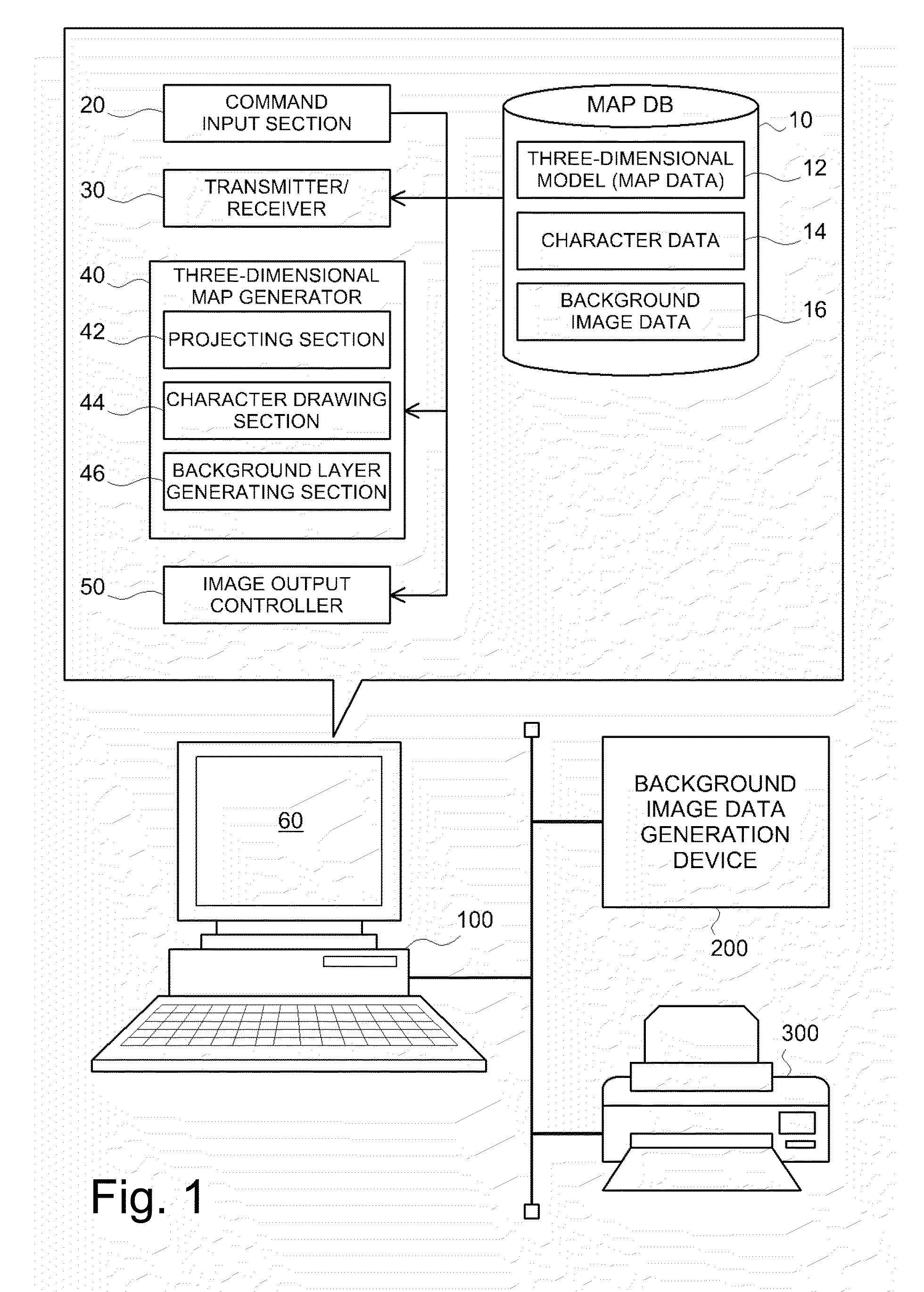
[0044]FIG. 1 is a diagram illustrating the general configuration of a three-dimensional map display system according to a first embodiment. As illustrated, this three-dimensional map display system includes a three-dimensional map display device 100, a background image data generation device 200 and a printer 300. In the three-dimensional map display system, the three-dimensional map display device 100 and the background image data generation device 200 may be configured integrally.

[0045]The three-dimensional map display device 100 includes a map database (DB) 10, a command input section 20, a transmitter / receiver 30, a three-dimensional map generator 40, an image output controller 50 and a display unit 60. These respective functional blocks are configured as software configuration by installing computer programs for implementing the respective functions in a personal computer including, for example, a CPU, a RAM, a ROM, a h...

Example

B. Second Embodiment

[0073]In the three-dimensional map display system of the first embodiment, the background image data 16 are stored in advance in the map database 10. In a three-dimensional map display system of a second embodiment, on the other hand, background image data 16 are generated appropriately by a background image data generation device 200A during the three-dimensional map display process. In the three-dimensional map display system of the second embodiment, there is no need to store the background image data 16 in the map database 10 of the three-dimensional map display device 100.

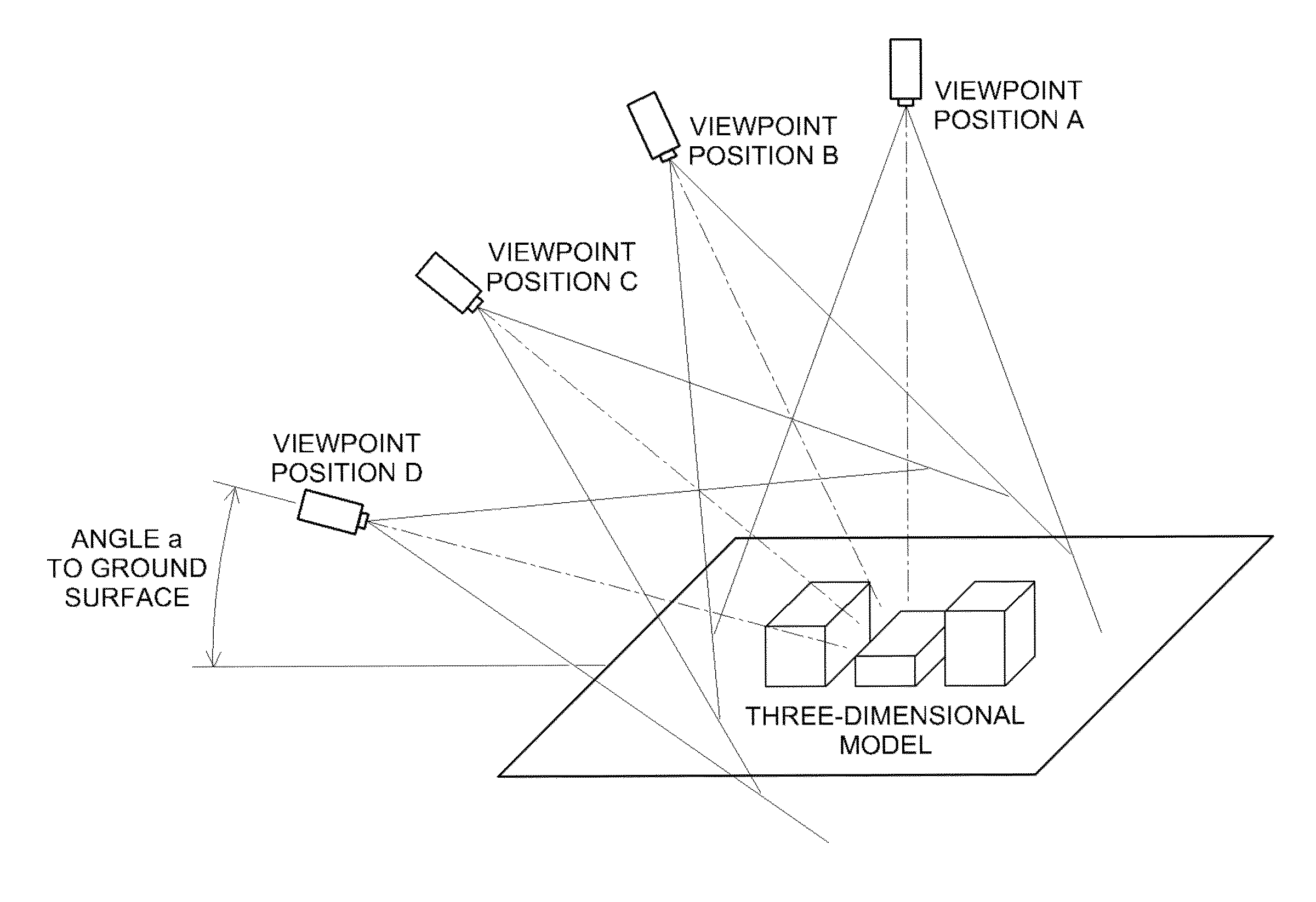
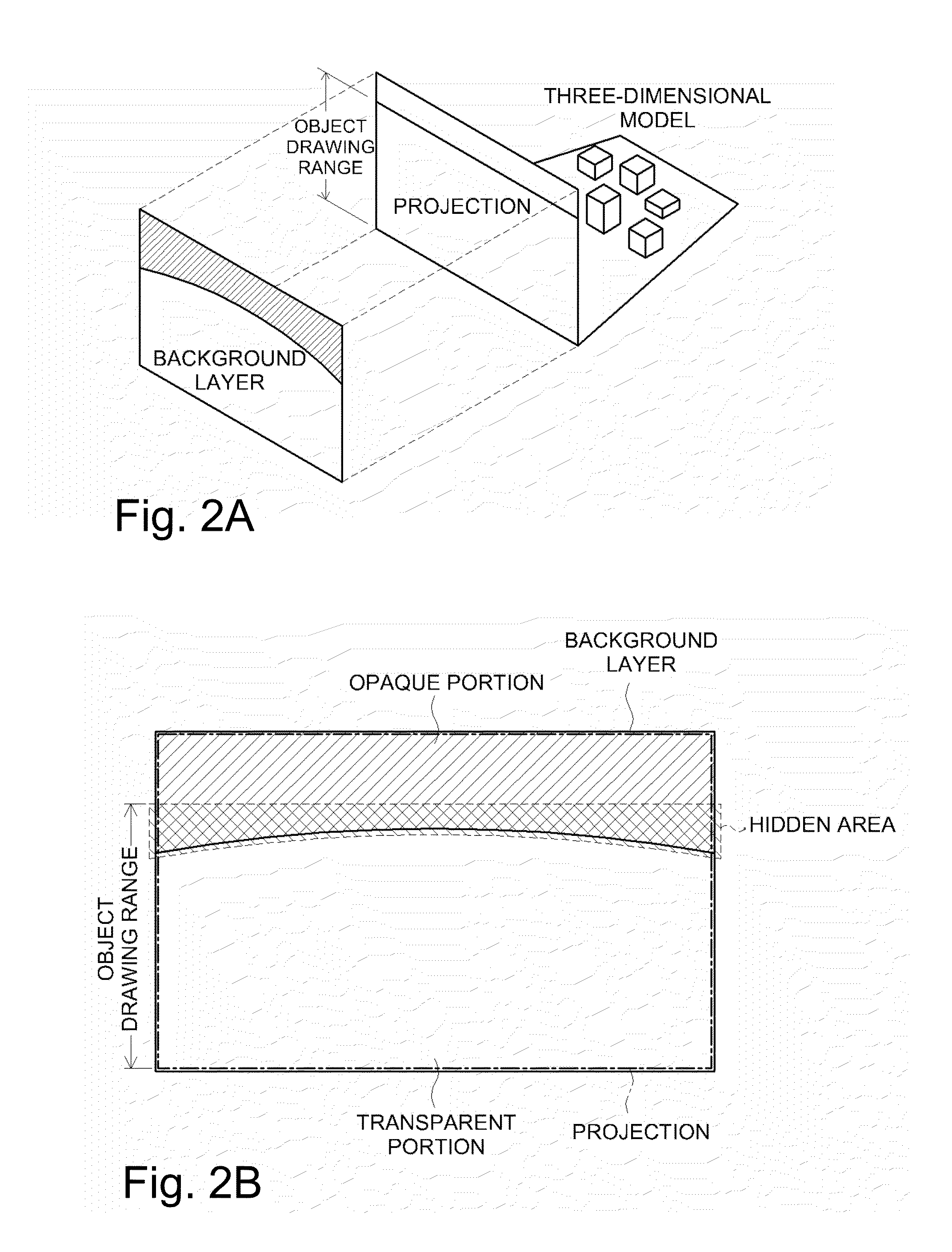
[0074]FIGS. 7A and 7B are diagrams schematically illustrating the relationship between the three-dimensional model, the viewpoint position and the object drawing range of a three-dimensional object image. As illustrated in FIG. 7A, the object drawing range of the three-dimensional object image increases with an increase in angle “a” between the gaze direction from the viewpoint position to ...


PUM


Abstract

A projection (projected image) is drawn by perspective projection of a three-dimensional model with a background image having improved reality. When a sightline of the perspective projection looks down from above, the projected image is drawn into an object drawing area which is a lower part of an image picture. A background layer representing the stratosphere is separately generated by two-dimensionally drawing a background image, in which the stratosphere (hatched area) is opaque, while the remaining area is transparent. The boundary between the opaque portion and the transparent portion forms a curved line that is convex upward to express a curved horizon. The background layer is superimposed in front of the projected image, not behind the projected image, thereby covering an upper edge portion of the projected image including a straight-lined upper edge, so as to provide a curved boundary realizing a curved pseudo horizon in the image picture.

Description

CLAIM OF PRIORITY[0001]This application is a Continuation of International Patent Application No. PCT / JP2014 / 001531, filed on Mar. 18, 2014, which claims priority to Japanese Patent Application No. 2013-061214, filed on Mar. 25, 2013, each of which is hereby incorporated by reference.BACKGROUND OF THE INVENTION[0002]1. Field of the Invention[0003]The present invention relates to a technology of outputting a three-dimensional image, in which a background image is superimposed on an image expressing an object three-dimensionally.[0004]2. Description of the Related Art[0005]Three-dimensional maps that three-dimensionally express features such as buildings and roads have become used widely. Bird's eye views that look down features in a wide area obliquely from above have also recently become popular. Such a three-dimensional map is often drawn by perspective projection of a three-dimensional model placed on the flat ground surface. A variety of techniques have been proposed to display a...

Claims


Application Information

Patent Timeline
IPC IPC(8): G06T11/60G06T17/05G09B29/00H04N5/272H04N9/04
CPCG06T11/60G06T17/05G09B29/005G06T2215/16H04N9/045G06T2219/2012H04N5/272G06F3/013G01C21/3638
Inventor KISHIKAWA, KIYONARITESHIMA, EIJIARAMAKI, MASATOSHIUCHINOUMI, MASASHINAKAGAMI, MASARUAZAKAMI, TATSUYA
Owner GEO TECHN LAB
Why Eureka
Try Eureka