Wideband Twin Beam Antenna Array

a twin beam antenna and wideband technology, applied in the field of radio communication, can solve the problems of high side and backlobe level, low cost, and inability to replace three antennas with six antennas

Active Publication Date: 2016-01-14
COMMSCOPE TECH LLC
View PDF29 Cites 37 Cited by
  • Summary
  • Abstract
  • Description
  • Claims
  • Application Information

AI Technical Summary

Benefits of technology

[0010]In another aspect of invention, a combination of 4 element and 5 element linear arrays is used to create a dual beam antenna with stabilized HPBW (+/−2 degree from nominal in 1.7 to 2.7 GHz), stabilized beam position (+/−1 degree from nominal) with low sidelobe level in azimuth an elevation plane for both beams.
[0011]According to one aspect of the invention, a wideband antenna includes a plurality of radiating elements arranged in an array and a feed network. The feed network has at least one input and a plurality of outputs coupled ...

Problems solved by technology

However, replacing three antennas with six antennas (each of which is 2 times wider than a common 65 degree antenna) is not a compact and low cost solution.
The main drawback of this prior art antenna is high levels of side and backlobes (about −1...

Method used


Image

  • Wideband Twin Beam Antenna Array
  • Wideband Twin Beam Antenna Array
  • Wideband Twin Beam Antenna Array

Examples


Embodiment Construction

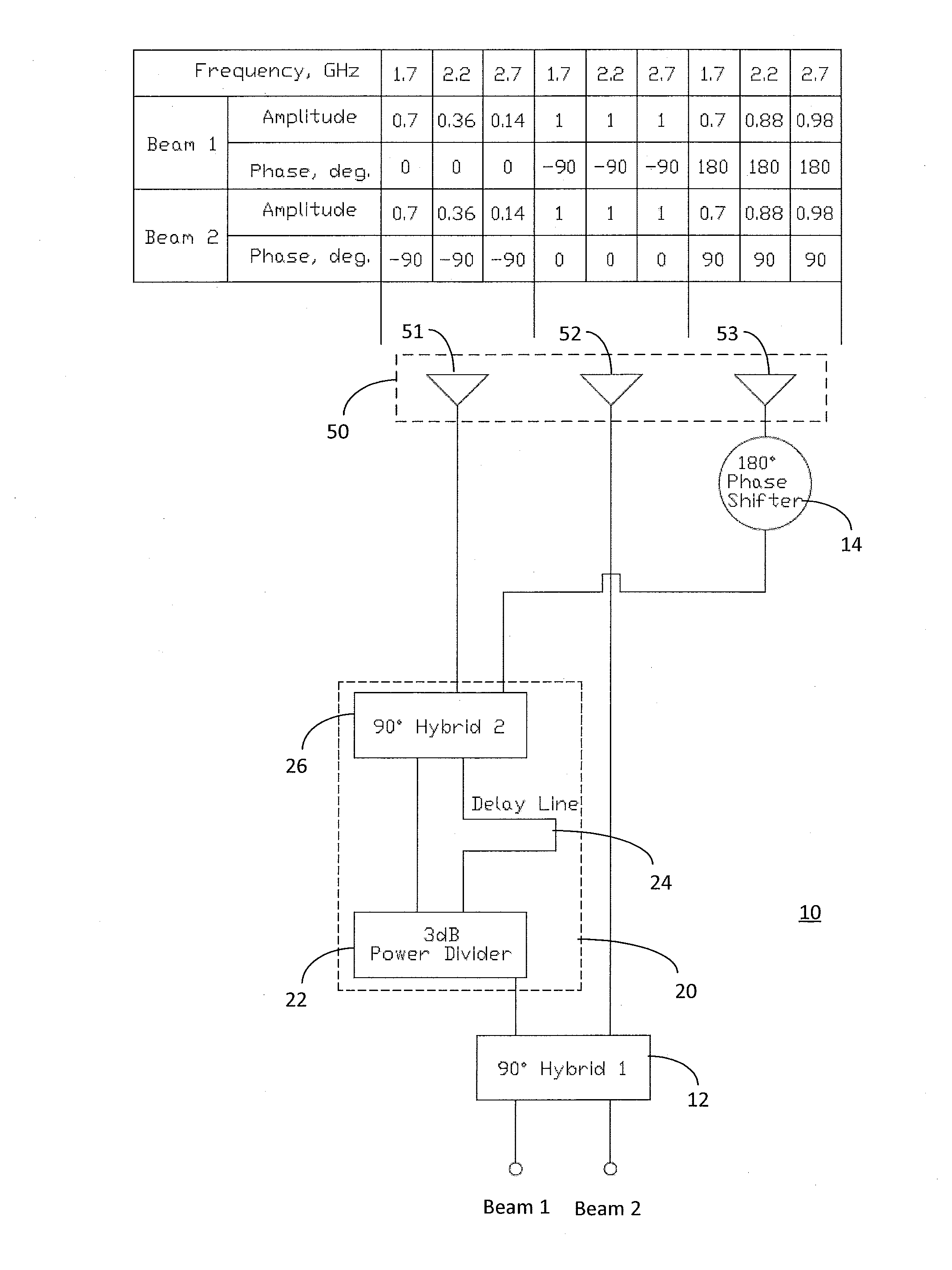
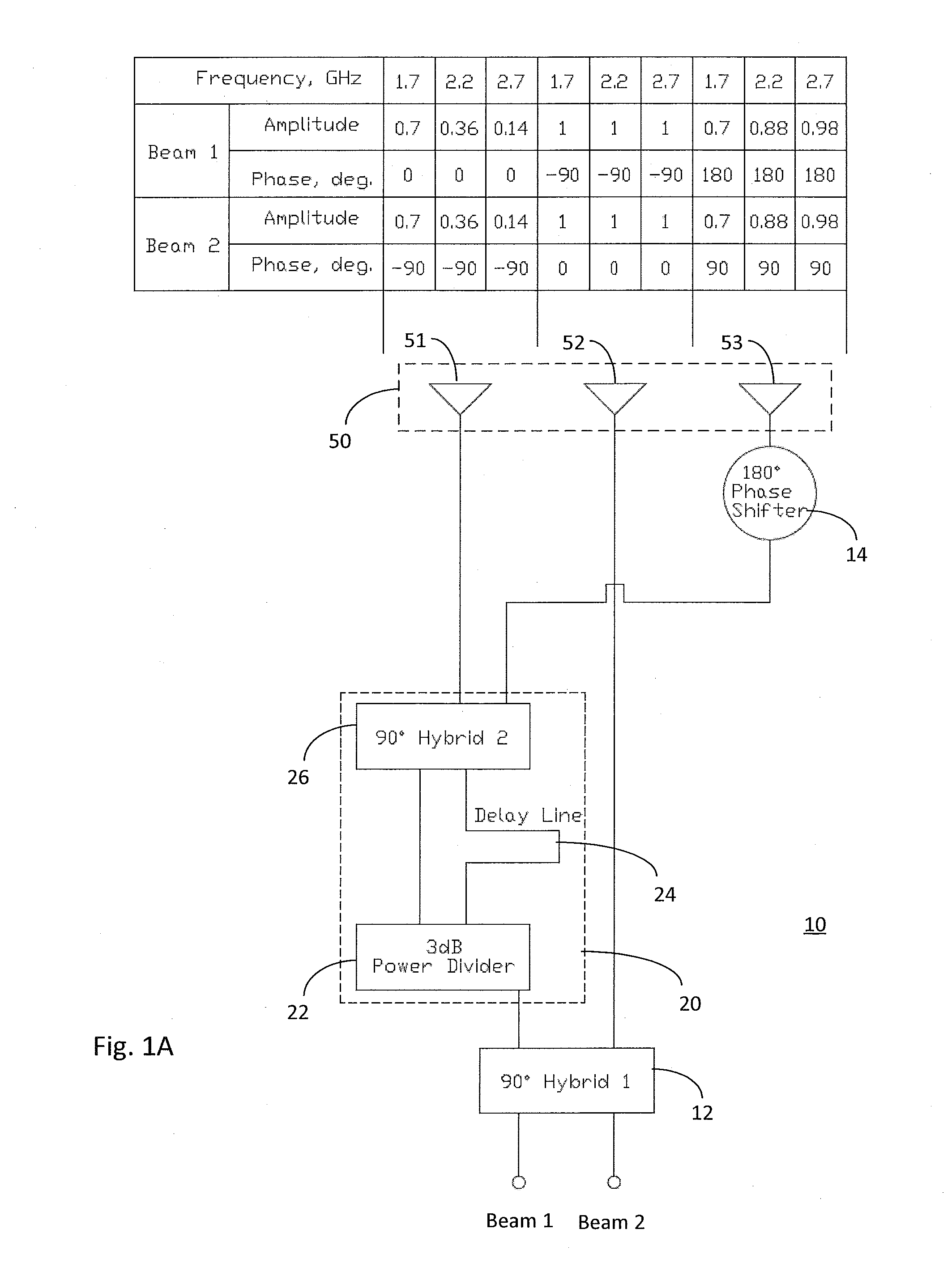
[0030]One aspect of the present invention is to compensate for the array factor of a phased-array multi-beam antenna with changing frequency. For example, FIG. 1A shows schematic diagram of beam forming network 10 and an array 50 of three radiating elements 51, 52 and 53. This example accepts two inputs, Beam 1 and Beam 2, and produces two beams. The beam forming network 10 comprises a 90° hybrid 12, a frequency dependent divider 20, and a 180° phase shifter 14. Inputs Beam 1 and Beam 2 are input to 90° hybrid 12. A first output of hybrid12 is coupled to the frequency dependent divider 20. A second output of hybrid 12 is coupled to a middle radiating element 52 of the array 50. Hybrid 12 may comprise a commercially available wideband 90° hybrids, for example Anaren X3C17-03WS-CT, which as a bandwidth of 690-2700 MHz, with almost constant 90° shift over all frequency band. The 3 dB power dividers, 16, 22 may be a multi-section Wilkinson dividers.

[0031]The frequency dependent divider ...


PUM


Abstract

A wideband antenna includes a plurality of radiating elements arranged in an array and a feed network. The feed network includes at least one frequency dependent power divider for varying the amplitude of a signal provided to at least two of the plurality of radiating elements as a function of a frequency of a signal. The feed network may further comprise a plurality of inputs and the antenna may produce a plurality of beams. The frequency dependent divider may comprise a power divider having a first output and a second output, a 90° hybrid, having a first input coupled to the first output of the power divider, and a second input, and a delay line, coupled between the second output of the power divider and the second input of the 90° hybrid.

Description

RELATED APPLICATIONS[0001]This application claims priority to U.S. Provisional Patent Application No. 61 / 845,616, filed Jul. 12, 2013 and titled “Wideband Twin Beam Antenna Array”, the entire disclosure of which is incorporated by reference.FIELD OF THE INVENTION[0002]The present invention generally relates to radio communication. More particularly, the invention relates to wideband multi-beam antennas for cellular communication systems.BACKGROUND OF THE INVENTION[0003]For common cellular applications where a given site has three sectors, each serviced by one antenna, each antenna usually has 65 degree azimuth Half Power Beamwidth (HPBW). Six sector cells may be employed at such sites to increase system capacity. Antennas with 33 degree and 45 degree HPBW are the most common for 6 sector applications. However, replacing three antennas with six antennas (each of which is 2 times wider than a common 65 degree antenna) is not a compact and low cost solution.[0004]Dual-beam (or multi-be...

Claims


Application Information

Patent Timeline
IPC IPC(8): H01Q21/00
CPCH01Q21/0075
Inventor TIMOFEEV, IGOR E.DENG, GANGYI
Owner COMMSCOPE TECH LLC
Why Eureka
Try Eureka