Tiled displays

a technology of display apparatus and display plate, which is applied in the direction of electrical apparatus casing/cabinet/drawer, identification means, instruments, etc., can solve the problems of prone to damage, large plasma and lcd display, and difficulty in providing large-area displays, so as to reduce the likelihood of a break in the conductivity of the track

Inactive Publication Date: 2016-01-14
FLEHKSENEHBL LTD
View PDF4 Cites 80 Cited by
  • Summary
  • Abstract
  • Description
  • Claims
  • Application Information

AI Technical Summary

Benefits of technology

[0033]There may further be provided the apparatus, wherein the extension of said first display unit comprises a track of a the electrode and a conducting polymer such as Pedot over the electrode track. Similarly as above, such a layer of polymer preferably deposited directly onto the track(s) reduces the likelihood of a break in conductivity of the track, for example due to flexing of the

Problems solved by technology

Difficulties are generally encountered in providing large area displays.
For example, large plasma and LCD displays are expensive and for outdoor application prone to damage.
However, they may suffer from one or more of the following disadvantages: difference in brightness and colour between neighbouring displays; large gap between neighbouring displays; emissive displays are difficult to read for outdoor applications.
However, they ma

Method used


Image

  • Tiled displays
  • Tiled displays
  • Tiled displays

Examples


Embodiment Construction

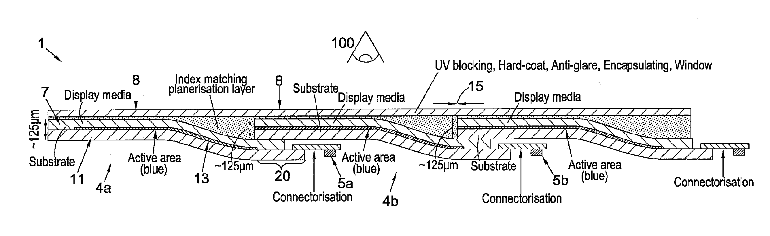
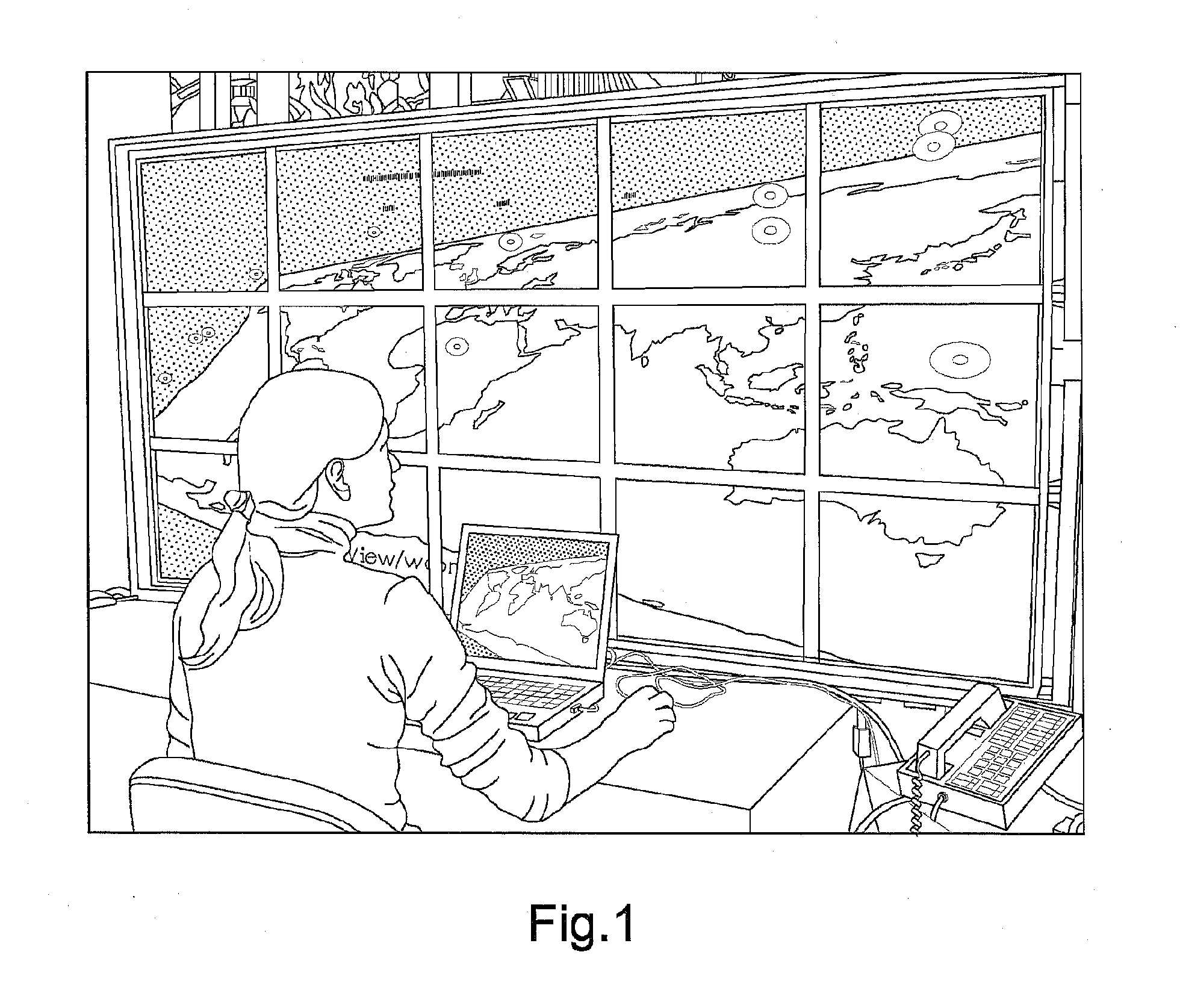
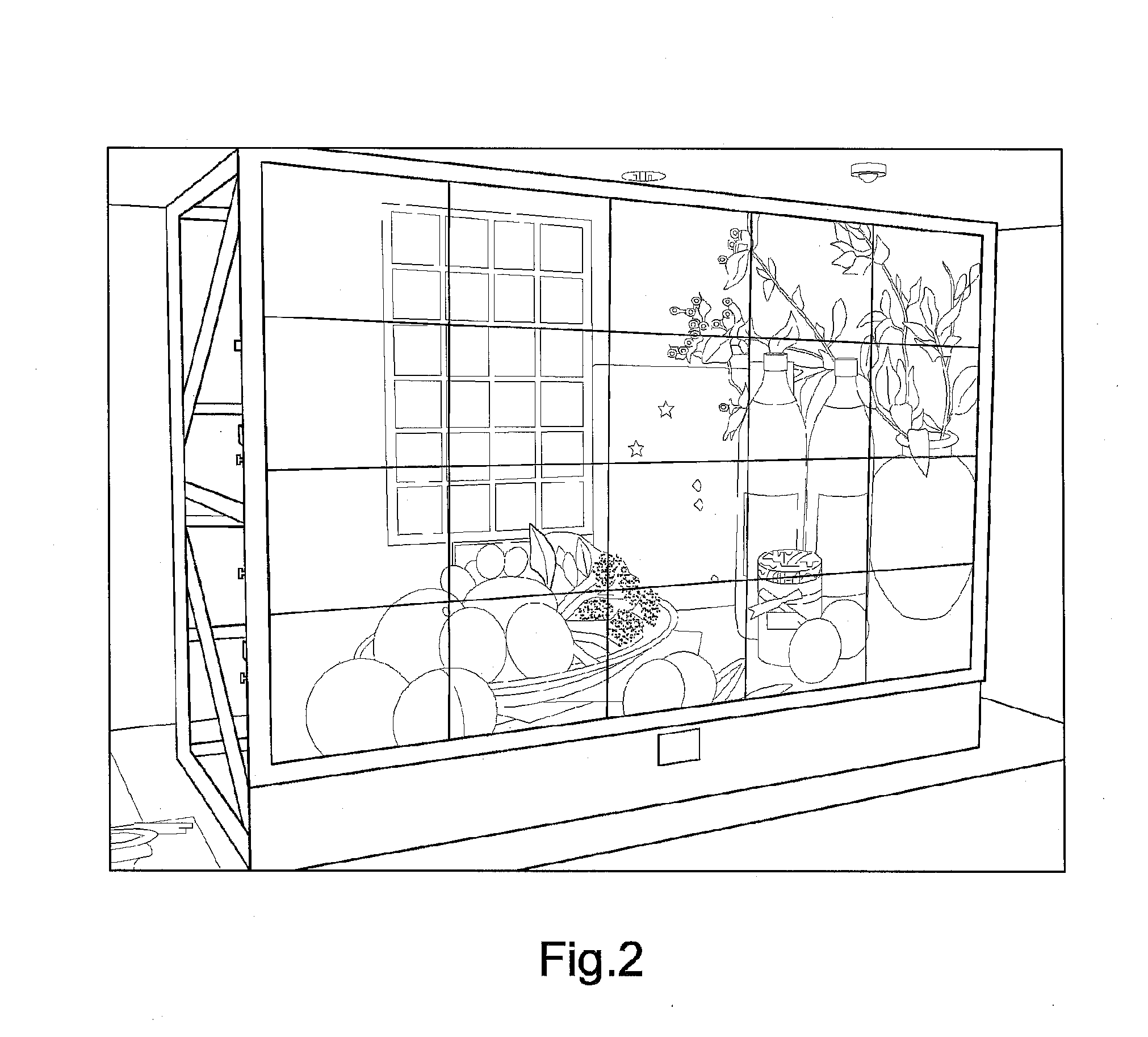
[0078]Embodiments generally relate to tiled displays using reflective displays, e.g., tiled e-paper displays. Advantageously, some embodiments may have a gap of less than 1 mm between neighbouring displays of the tiled display. Thus, an image may be displayed substantially continuously across the full display. Additionally or alternatively, an advantage may be to connect source and control electrodes (tracks) such as source and gate lines, of the multiple display units together to avoid or reduce any need to connect driver electronics to each individual display unit.

[0079]By using a reflective display medium, an embodiment may be battery operated and therefore can be stand alone, which is of clear advantage for remote locations. Such medium may also allow the display to be readable in daylight. Furthermore, by providing such a medium with a flexible backplane, an embodiment may be more resilient against vandalism.

[0080]According to a first option, the display units, otherwise referr...


PUM

PropertyMeasurementUnit
Angleaaaaaaaaaa
Widthaaaaaaaaaa
Flexibilityaaaaaaaaaa

Abstract

The application generally relates to reflective display apparatus having a flexible display panel and driver electronics to drive the flexible display panel and methods of forming a flexible display unit for a reflective display apparatus having a flexible display panel and driver electronics to drive the flexible display panel, and more particularly to tiled displays comprising reflective, e.g., electrophoretic, display medium. One embodiment is a reflective display apparatus having a flexible display panel and driver electronics to drive the flexible display panel, the flexible display panel comprising at least first and second flexible display units, the driver electronics configured to drive said flexible display units to display respective image regions, wherein said first and second said flexible display units are adjacent and each comprise: a display layer comprising display medium; and a control layer having a backplane and a substrate to support the backplane, the backplane to control said display layer to display an image region, wherein: the driver electronics comprises a first drive electronics unit to control the backplane of said first display unit and a second drive electronics unit to control the backplane of said second display unit, said first drive electronics unit disposed on said first display unit and said second drive electronics unit disposed on said second display unit, a said drive electronics unit is mounted behind a said substrate of a said adjacent display unit to thereby substantially hide the said drive electronics unit from a user viewing a said image region displayed on the said adjacent display unit, wherein the display layer of the said adjacent display unit is in front of the said substrate, the said drive electronics unit attached to a said adjacent display unit.

Description

FIELD OF THE INVENTION[0001]This invention generally relates to reflective display apparatus having a flexible display panel and driver electronics to drive the flexible display panel and methods of forming a flexible display unit for a reflective display apparatus having a flexible display panel and driver electronics to drive the flexible display panel, and more particularly to tiled displays comprising reflective, e.g., electrophoretic, display medium.BACKGROUND TO THE INVENTION[0002]Difficulties are generally encountered in providing large area displays. For example, large plasma and LCD displays are expensive and for outdoor application prone to damage. Tiled displays may be present a more economically viable alternative, for example by allowing higher manufacturing yield. Such tiled displays comprise multiple display units arranged to provide a larger display that can display an image over a correspondingly large area, e.g., >2 m2. LCD, rear projection and LED tiled display...

Claims


Application Information

Patent Timeline
IPC IPC(8): H05K1/02G02B26/00G02F1/167H01L27/32H05K5/00
CPCH05K1/028H05K5/0017H01L27/3293G02B26/005G02F1/167G02F1/133305G02F1/13336G02F1/13338G02F1/133553G02F1/13452G02F2203/02G09G3/3648G09G2300/026G09G3/035H10K59/18G02F1/1335G09G2380/02G02F1/133365G09F9/3023B32B2457/20G09F9/3026G09F9/301B32B2457/206G09F9/302
Inventor JONGMAN, JANREEVES, WILLIAM
Owner FLEHKSENEHBL LTD
Why Eureka
Try Eureka