Hybrid capacitor and method of manufacturing a capacitor

a hybrid capacitor and capacitor technology, applied in the field of hybrid capacitors, can solve the problems of poor process reliability, high capacitance of liquid electrolytic capacitors, complicated manufacturing stages, etc., and achieve the effects of low esr, enhanced performance, and improved quality

Active Publication Date: 2018-09-04
KEMET ELECTRONICS CORP
View PDF12 Cites 7 Cited by
  • Summary
  • Abstract
  • Description
  • Claims
  • Application Information

AI Technical Summary

Benefits of technology

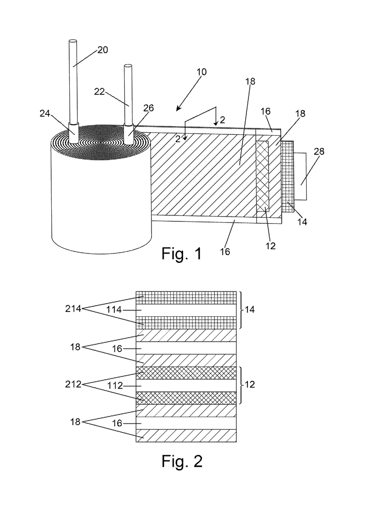
[0023]FIGS. 6-10 are graphical representations illustrating advantages of the invention.
[0024]FIG. 11 is a cross-sectional schematic view of an embodiment of the invention.DESCRIPTION
[0025]The instant invention is specific to a capacitor, comprising a solid conductive polymer electrolyte and an optional liquid electrolyte interspersed in a wound capacitor comprising interleaved anode, cathode and separator. More specifically, the present invention is directed to a capacitor, and a method of making a capacitor, which is not limited in size, exhibits improved quality and is suitable for manufacturing axial capacitors. More specifically, the instant invention allows for the manufacture of capacitors with enhanced performance, specifically low ESR and high capacitance, without limit to case size and in virtually any design including axial, radial, planar, etc.
[0026]An element of the instant invention is the utilization of anodes, cathodes and separators which are pre-treated with conductive polymer either as a coating or, particularly in the case the separator, being impregnated with conductive polymer. The pre-treatment with conductive polymer is done before the working element is formed thereby allowing for an improved polymer layer relative to the prior art. Since the method is not limited to polymer diffusion into the windings the instant method eliminates capacitor size restrictions and significantly increases volumetric efficiency defined as capacitance as a function of capacitor size.
[0027]The problem associated with solid electrolyte distribution over the entire electrode surface is eliminated by the formation of a conductive porous layer prior to winding thereby providing a conductor between the anode conductive polymer coating and cathode conductive polymer coating whereby conventional liquid electrolyte can flow through the conductive porous layer to provide typical functions thereof such as self-healing. As the conductive polymeric layers are formed prior to winding the only impregnation necessary after winding is the liquid electrolyte which is more mobile and can more easily diffuse, or migrate, into the interstitial area. This allows for a wide variety of designs since the liquid electrolyte is not impeded from migrating into even the most remote interstitial spaces. Furthermore, the prior problem of conductivity break, essentially an incomplete electrical conductive pathway, between polymer coated electrodes common with the art is mitigated by substituting the typical non-conductive separator with a conductive porous layer between the anode conductive polymer coating and cathode conductive polymer coating.
[0028]The invention will be described with reference to the various figures forming an integral non-limiting component of the disclosure. Throughout the disclosure similar elements will be numbered accordingly.

Problems solved by technology

For example, liquid electrolytic capacitors have a high capacitance but a poor Equivalent Series Resistance (ESR) due to poor conductivity of the electrolyte, typically not above about 0.015 S / cm, whereas conductive polymers have a high conductivity, up to 600 S / cm, and therefore capacitors utilizing conductive polymeric cathodes have a much lower ESR.
In-situ polymerization is a complex method with many problems including contamination of the final product by monomer and oxidizer and the work environment conditions are complex leading to poor process reliability.
Manufacturing stages are complicated due to limitations associated with the rate and efficiency of diffusion through the working element.
Filtration of polymeric particles and counterions by the separator limits effective diffusion thereby limiting the length of the working element.
As a result, only small capacitor sizes have been successfully achieved.
Large capacitors have proven difficult to make.
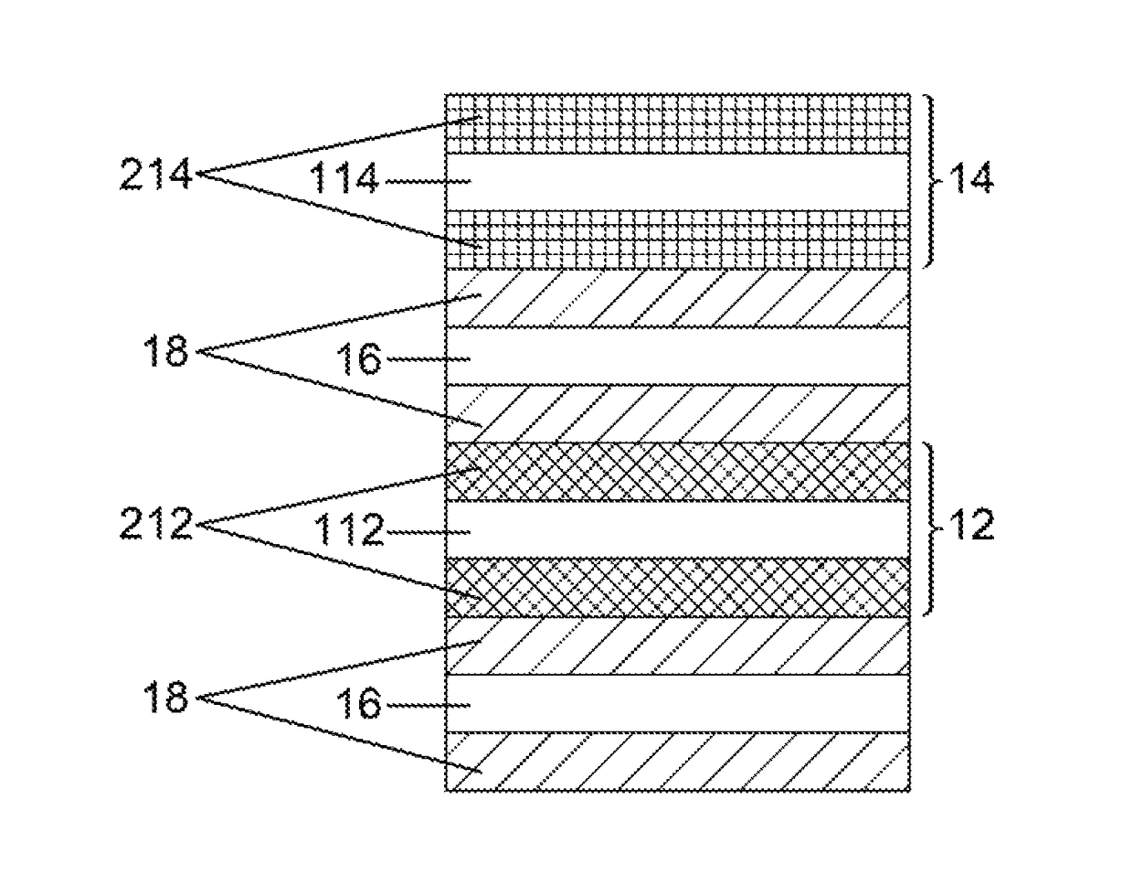
Due to manufacturing limitations, hybrid capacitors have been primarily radial capacitors as the manufacturing process is not suitable for small axial capacitors.
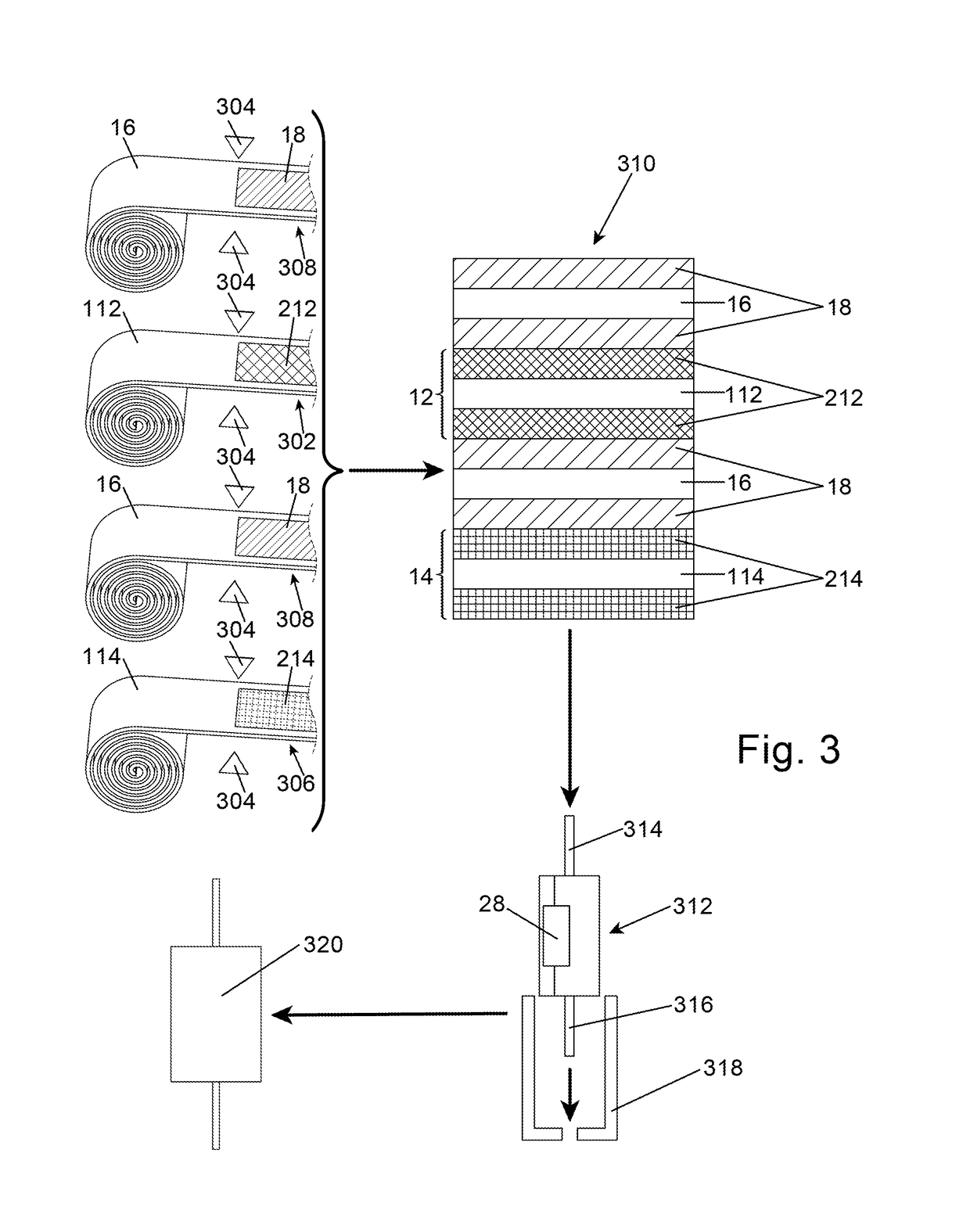
With axial capacitors the bottom tab, or lead, will necessarily be dipped in the polymer precursor or polymer slurry thereby resulting in a polymer coated tab which causes problems with subsequent processing.
Furthermore, it is virtually impossible to apply voltage across the capacitor, such as to form polymer in-situ or to heal damaged sites, since the bottom tab will be in the solution.
In spite of the ongoing efforts, those of skill in the art still do not have a suitable method for forming a hybrid capacitor, and a hybrid capacitor formed thereby, suitable for large case sizes or suitable for use in manufacturing axial capacitors.

Method used


Image

  • Hybrid capacitor and method of manufacturing a capacitor
  • Hybrid capacitor and method of manufacturing a capacitor
  • Hybrid capacitor and method of manufacturing a capacitor

Examples


Embodiment Construction

(I-1)

[0053]Anodized aluminum anode foils and aluminum cathode foils of sizes and capacitance rating as shown in Table 1 were heat treated at 300±5° C. for 30±5 min. The anode foil was subjected to a first edge formation treatment by immersing in 5% oxalic acid at 30±5° C. at a voltage of 5 mA / cm2. The foil was washed for a minimum of 5 minutes and dried at 125±5° C. for 25-30 min. The anode foil was heat treated at 300±5° C. for 30±5 min followed by a second edge formation in 1% ammonium citrate at a voltage of 1.5 mA / cm2 at 50±5° C. followed by washing for at least 5 min and drying at 125±5° C. for 25-30 min. The anode and cathode were subjected to a silane treatment for 15-30 sec. in a solution comprising 4935 ml+ / −50 ml DI Water, 15 ml+ / −0.5 ml acetic acid and 50 ml+ / −1 ml 3-glycidoxypropyltrimethoxysilane at a pH of 3.0+ / −1.0. The anode and cathode foils were again heat treated 300±5° C. for 30±5 min. The anode was anodized again to oxidize the edges in 0.1% ammonium phosphate a...


PUM

PropertyMeasurementUnit
wt %aaaaaaaaaa
diameteraaaaaaaaaa
diameteraaaaaaaaaa

Abstract

An improved capacitor is described herein. The capacitor comprises a working element wherein the working element comprises an anode comprising a dielectric thereon and an anode conductive polymer layer on the dielectric. The capacitor also includes a cathode comprising a cathode conductive polymer layer and a conductive separator between the anode and said cathode. An anode lead is in electrical contact with the anode and a cathode lead is in electrical contact with the cathode.

Description

BACKGROUND[0001]The present invention is related to capacitors comprising a solid conductive polymeric electrolyte and an optional liquid electrolyte. More specifically, the present invention is related to a capacitor comprising a conductive separator and a method of forming the hybrid capacitor with improved conductive polymer coverage within the interstitial portions of a wound structure.[0002]Capacitors have historically been defined within two general types with one type utilizing a liquid electrolyte and the other type utilizing a solid electrolyte. Liquid electrolyte capacitors, generally, comprise a layered structure typically as a winding with an anode conductor, a cathode conductor and an interleaved separator immersed in a liquid electrolyte all sealed within a container. Solid electrolyte capacitors, generally, include a conductive monolith or foil with a dielectric layer thereon and a solid cathode, such as conductive polymer or manganese dioxide, on the dielectric. Both...

Claims


Application Information

Patent Timeline
Patent Type & Authority Patents(United States)
IPC IPC(8): H01G9/025H01G9/02H01G9/15H01G11/04H01G11/24H01G11/30H01G11/52H01G11/86H01G9/00H01G9/008H01G9/028
CPCH01G11/04H01G9/008H01G9/0036H01G9/151H01G11/30H01G11/52H01G11/86H01G11/24H01G9/028
Inventor ANDORALOV, VICTORDEISENHOFER, RALF
Owner KEMET ELECTRONICS CORP
Why Eureka
Try Eureka