Drawing and Straightening Apparatus for Metal Wire, and Corresponding Drawing and Straightening Method

a technology of drawing and straightening apparatus and metal wire, which is applied in the direction of metal-working feeding devices, wire straightening devices, manufacturing tools, etc., can solve the problems of increasing difficulty, increasing problem, and more obvious problems, so as to reduce internal tension, reduce the possibility of wire rotation, and high extraction force

Active Publication Date: 2016-01-21
M E P MASCH ELECTRONICS PIEGATRICI SPA
View PDF1 Cites 5 Cited by
  • Summary
  • Abstract
  • Description
  • Claims
  • Application Information

AI Technical Summary

Benefits of technology

[0023]The straightening only unit has a configuration generally the same type as the drawing unit, and exerts on the metal wire in transit a plastic deformation such as to reduce the internal tensions present in the latter.
[0024]In particular, the simultaneous presence of the drawing unit with the large size main roll and corresponding contrast rolls, and the straightening only unit located upstream, also having a large size main roll and contrast roll, assists the advance of the wire and in particular its unwinding from the reel, if present.
[0025]In fact, on the advancing wire at least two consecutive loops are made, adjustable in amplitude, caused by the presence of the contrast rolls, around part of the periphery of the large size main roll. The formation of loops at the same time guarantees high extraction forces, considerably reducing the possibility of rotation of the wire.
[0026]This solution is particularly advantageous from the production point of view, since the number of different components and the complexity of production are reduced.
[0027]According to some forms of embodiment of the invention, the drawing unit and / or the straightening only unit comprises at least a straightening member, disposed upstream or downstream of the first main roll and / or a second main roll, and also provided with respective rolls. The function of the straightening member is to increase the deformation effect induced on the metal wire and also, if it is disposed upstream of the first and / or second main roll, to guide its introduction into one of the latter.

Problems solved by technology

The difficulties encountered in the drawing and straightening step of the metal wire arriving from rolling are known, which difficulties increase when the metal wire is fed to the shaping machine from a roll.
This problem increases in the case of metal wire arriving from a roll, since the wire should be extracted from a reel that may or may not rotate around its own axis in order to facilitate the unwinding of the wire.
These problems are more evident in the case of metal wires for reinforcement rods.
Due to the surface ribs present, such metal wires have discontinuous surfaces and a shape that is not always perfect.
It is therefore obvious that a simple bending operation made on the metal wire is conditioned by the tensions present therein, so that the possible geometric forms made with the metal wire not only do not keep the desired geometric disposition, but do not even maintain the flat spatial disposition.
The stirrups are therefore unusable, or are poor quality and low reliability when installed, and generally speaking should be discarded.
In addition, in the case of metal wire for reinforcement rods, given the continuous variation in its section, the correct and accurate drawing and / or straightening becomes uncertain, not constant and not uniform.
When the drawing and straightening means do not perform their function constantly and without errors, it is not possible either to make stirrups or other shapes of metal wire with the desired sizes, or to make a plurality of identical stirrups, whether in sequence or not.

Method used


Image

  • Drawing and Straightening Apparatus for Metal Wire, and Corresponding Drawing and Straightening Method
  • Drawing and Straightening Apparatus for Metal Wire, and Corresponding Drawing and Straightening Method

Examples


Embodiment Construction

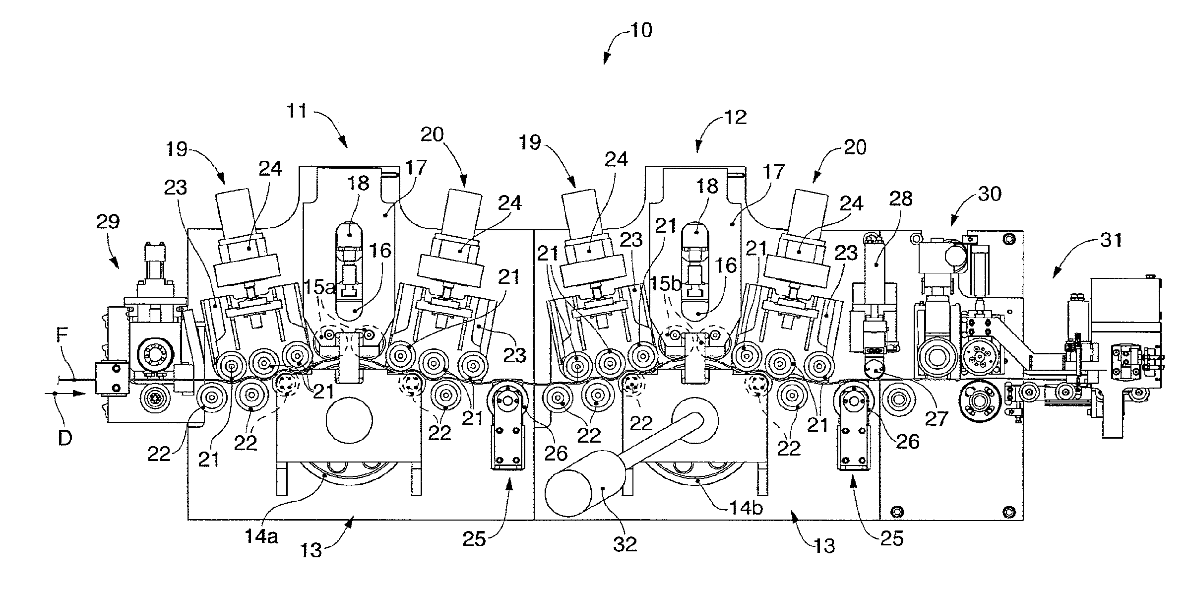
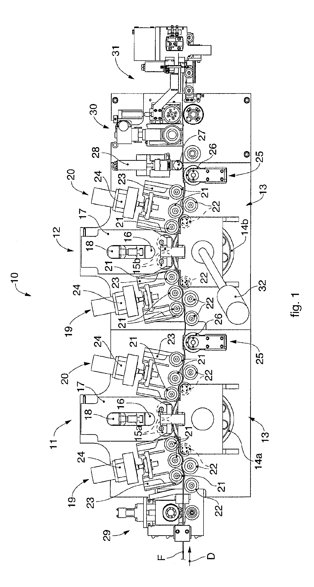
[0032]With reference to FIG. 1, a drawing and straightening apparatus 10 according to the present invention can be associated with a shaping machine, not shown in the drawings, for working oblong metal products such as metal wires F.

[0033]The drawing and straightening apparatus 10 is suitable to perform both drawing functions and also straightening functions simultaneously.

[0034]The drawing and straightening apparatus 10 in this case comprises two distinct operating units, respectively a first operating unit 11, or straightening unit, configured to perform only straightening and anti-rotation operations on the metal wire F, and a second operating unit 12, or drawing unit, configured to exert on the metal wire F not only a straightening and anti-rotation action but also a drawing action in a direction of advance D, which substantially coincides with the direction of advance that a metal wire F already linearized would have, in order to reach the devices disposed downstream.

[0035]The ...


PUM

PropertyMeasurementUnit
diameteraaaaaaaaaa
diameteraaaaaaaaaa
diameteraaaaaaaaaa

Abstract

Apparatus for drawing and straightening at least a metal wire, comprising a drawing unit of the metal wire along a direction of advance which comprises a first motorized main roll, on part of the periphery of which first idle contrast rolls are disposed, with a smaller diameter than the first main roll. The apparatus also comprises a straightening only unit of the metal wire, independent from the drawing unit, disposed along the direction of advance and upstream of the drawing unit, the straightening only unit comprising a second idle main roll, on part of the periphery of which second idle contrast rolls are disposed, with a diameter smaller than the second main roll.

Description

FIELD OF THE INVENTION[0001]The present invention concerns a drawing and straightening apparatus for feeding machines that work oblong metal products such as bars, round pieces or metal wire, of the type usable to make reinforcements for the building trade.[0002]In particular, the drawing and straightening apparatus according to the present invention is preferentially applied, but not only, to bending / shaping machines that can work simultaneously two metal wires at a time, performing a constantly uniform, coordinated and simultaneous feed.[0003]The invention also concerns the connected drawing and straightening method.BACKGROUND OF THE INVENTION[0004]Bending / shaping or stirrup-making machines are known, hereafter shaping machines. The bending units or devices of such machines are fed with oblong metal products such as metal wire from a roll, or precut bars, to make reinforcement stirrups for the building trade. Hereafter these base materials, whether they come from a roll or are alr...

Claims


Application Information

Patent Timeline
Patent Type & Authority Applications(United States)
IPC IPC(8): B21F1/02B21C19/00B21F23/00
CPCB21C19/00B21F23/00B21F1/02B21D43/02B21C1/16
Inventor DEL, FABRO, GIORGIO
Owner M E P MASCH ELECTRONICS PIEGATRICI SPA
Why Eureka
Try Eureka