Tank welding fixture

Inactive Publication Date: 2016-01-21
LINCOLN GLOBAL INC
View PDF15 Cites 47 Cited by
  • Summary
  • Abstract
  • Description
  • Claims
  • Application Information

AI Technical Summary

Benefits of technology

[0009]In various embodiments of the above example, after welding has been completed, the method further comprises: raising the at least one vertically adjustable pipe stand to support the object; linearly adjusting the movable table on at least one of the headstock and the tailstock to finely increase the distance between the headstock and the tailstock; and linearly adjusting at least one of the headstock and the tailstock along the rail system to coarsely increase the distance between the headstock and the tailstock, wherein the coarse adjustment or fine adjustment causes at least one compression clamping member on each of the headstock and the tailstock to r

Problems solved by technology

However, such fixtures are not able to easily and appropriately account for variations in diameters and lengths of tanks, for example, within desig

Method used


Image

  • Tank welding fixture
  • Tank welding fixture
  • Tank welding fixture

Examples


Example

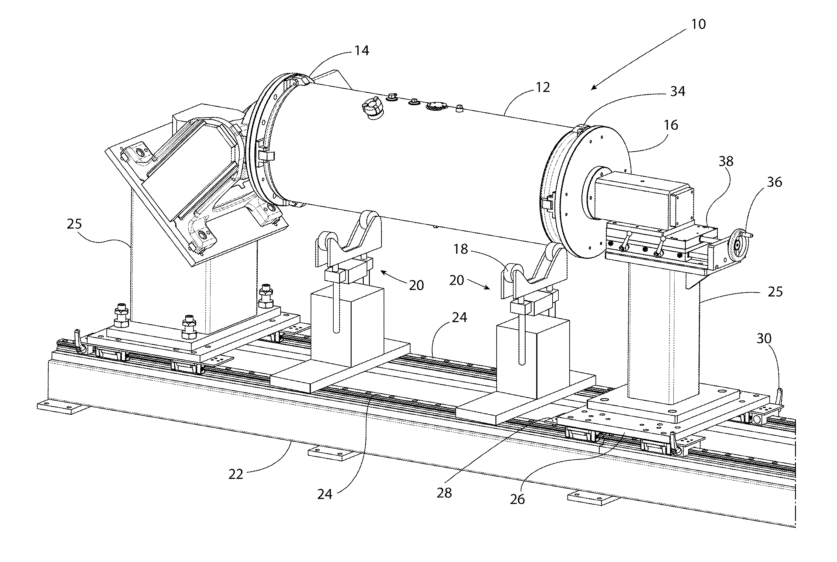
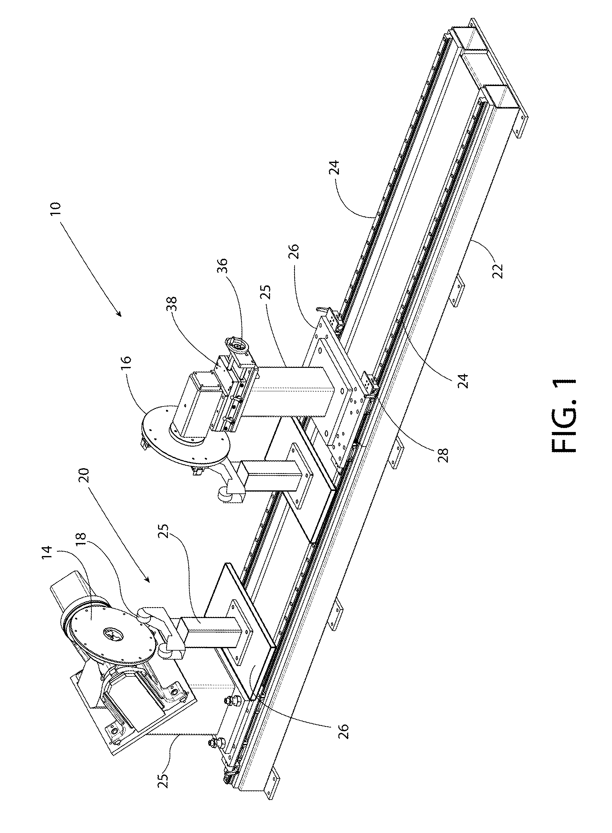
[0019]Turning now to a description of the figures, FIGS. 1-4 show an example welding fixture 10. The welding fixture 10 is configured to support a generally cylindrical object, such as a tank, pressure vessel, or the like, during a welding operation. FIG. 1 shows the welding fixture 10 with no object present, whereas FIG. 2 shows a similar view of the welding fixture 10 while supporting a tank 12. While the welding fixture 10 is generally described herein with respect to a tank, it should be noted that this not intended to be a limiting feature and that the welding fixture 10 may be used with any generally cylindrical object. The welding fixture 10 includes a headstock 14, a tailstock 16, and one or more pipe stands 20 for supporting the tank 12. The pipe stands 20 can be used to support the tank 12 prior to, during, and / or subsequent to a welding operation. The pipe stands 20 can include a roller head 18 having, for example, roller bearings, that allow the tank 12 to rotate within ...


PUM


Abstract

A welding fixture and method allow for both coarse and fine adjustments of headstocks and tailstocks for securing a tank or other cylindrical-like object within a welding fixture. Coarse adjustment is provided by adjusting the headstock and/or tailstock linearly along a rail system. Find adjustment is provided by linearly adjusting a movable table on which the headstock and/or tailstock rest. The headstock and tailstock may also have compression damping members for securing the tank to the headstock and tailstock. Pipe stands are also provided for supporting the tank before, during, and after the welding process.

Description

CROSS-REFERENCE TO RELATED APPLICATIONS[0001]This application claims priority to U.S. Provisional Application Ser. No. 62 / 026,083, filed on Jul. 18, 2014, entitled “TANK WELDING FIXTURE”, the entirety of which is incorporated herein by reference.BACKGROUND OF THE INVENTION[0002]The present disclosure relates to welding fixtures. In particular, fixtures for supporting generally cylindrical objects during welding. Examples of such cylindrical objects include tanks, pressure vessels, and the like.[0003]Currently, tanks and other similar cylindrical objects can be formed by using robotic welding arms with the tank or object held in a welding fixture. The robotic welding arm may move to desired coordinates, while the tank may be rotated about its length in the fixture. Given this configuration, the robotic arm is able to reach and weld any necessary locations. However, such fixtures are not able to easily and appropriately account for variations in diameters and lengths of tanks, for exa...

Claims


Application Information

Patent Timeline
IPC IPC(8): B23K37/053B23K37/04
CPCB23K37/0452B23K37/0538
Inventor BEATTY, JOHNNY W.WHITWORTH, TRAVIS G.WHAN, MICHAELSIMONS, BRIAN
Owner LINCOLN GLOBAL INC
Why Eureka
Try Eureka