Spring-loaded insulation piercing electrical connector

a technology of electrical connectors and springs, which is applied in the manufacture of contact members, contact members penetrating/cutting insulation/cable strands, and unstripped conductor connection apparatus, etc. it can solve the problems of increasing the operating cost of the utility company, complex hot stick maneuvering, etc., and achieve the effect of facilitating the description

Active Publication Date: 2016-01-21
HUBBELL INC
View PDF4 Cites 10 Cited by
  • Summary
  • Abstract
  • Description
  • Claims
  • Application Information

AI Technical Summary

Benefits of technology

[0008]As used in this application, the terms “front,”“rear,”“upper,”“lower,”“upwardly,”“downwardly,” and other orientational descriptors are intended to facilitate the description of the exemplary embodiments of the present invention, and are not intended to limit the structure of the exemplary embodiments of the present invention to any particular position or orientation.

Problems solved by technology

One disadvantage associated with conventional power line clamp connectors is that complex maneuvering of a utility lineman's hot stick is required to manipulate an eyebolt of the clamp to connect to the conductors.
As maintenance and installation operations become increasingly difficult, the added time required for these operations can increase operating costs for the utility company.

Method used


Image

  • Spring-loaded insulation piercing electrical connector
  • Spring-loaded insulation piercing electrical connector
  • Spring-loaded insulation piercing electrical connector

Examples


Embodiment Construction

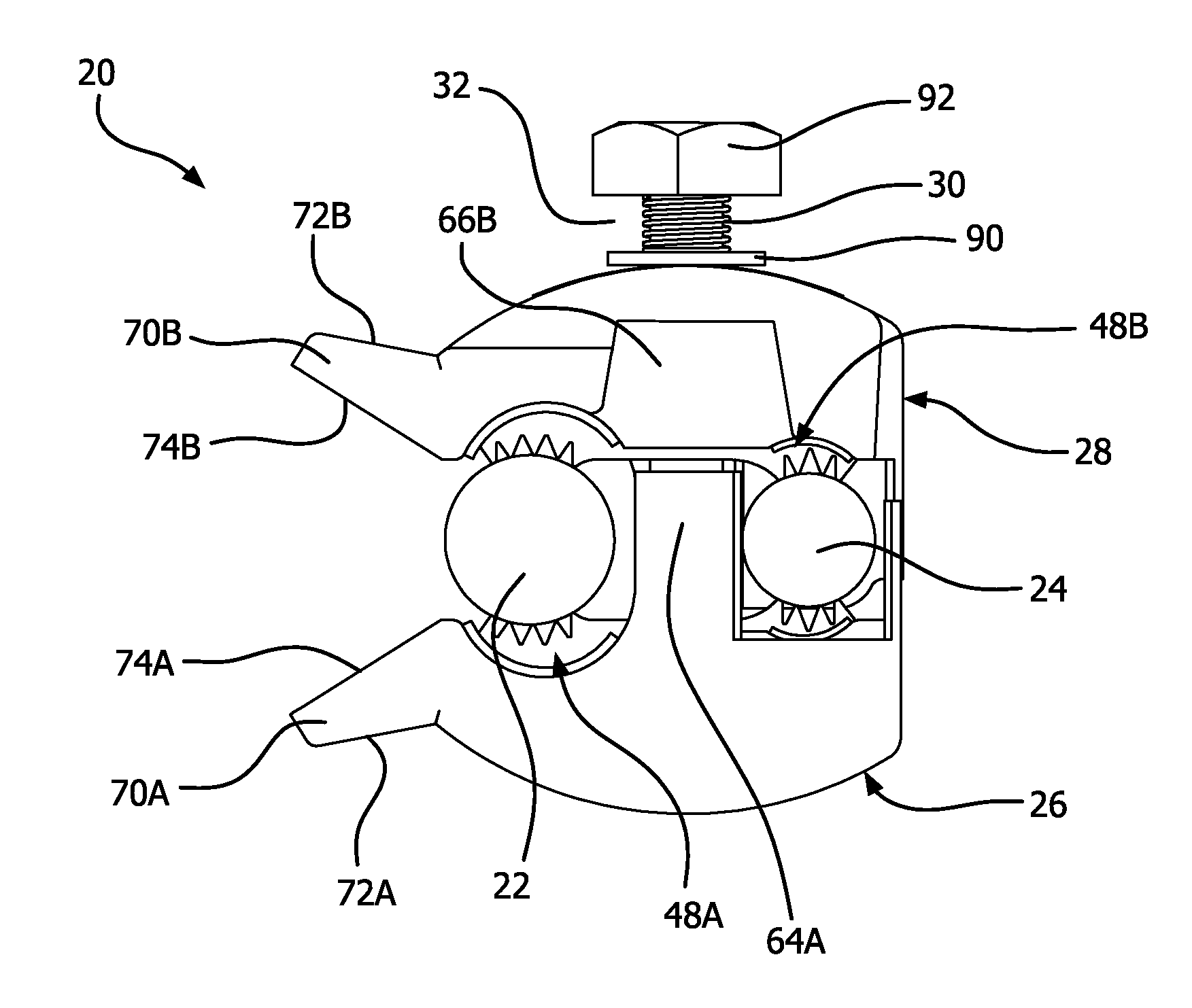
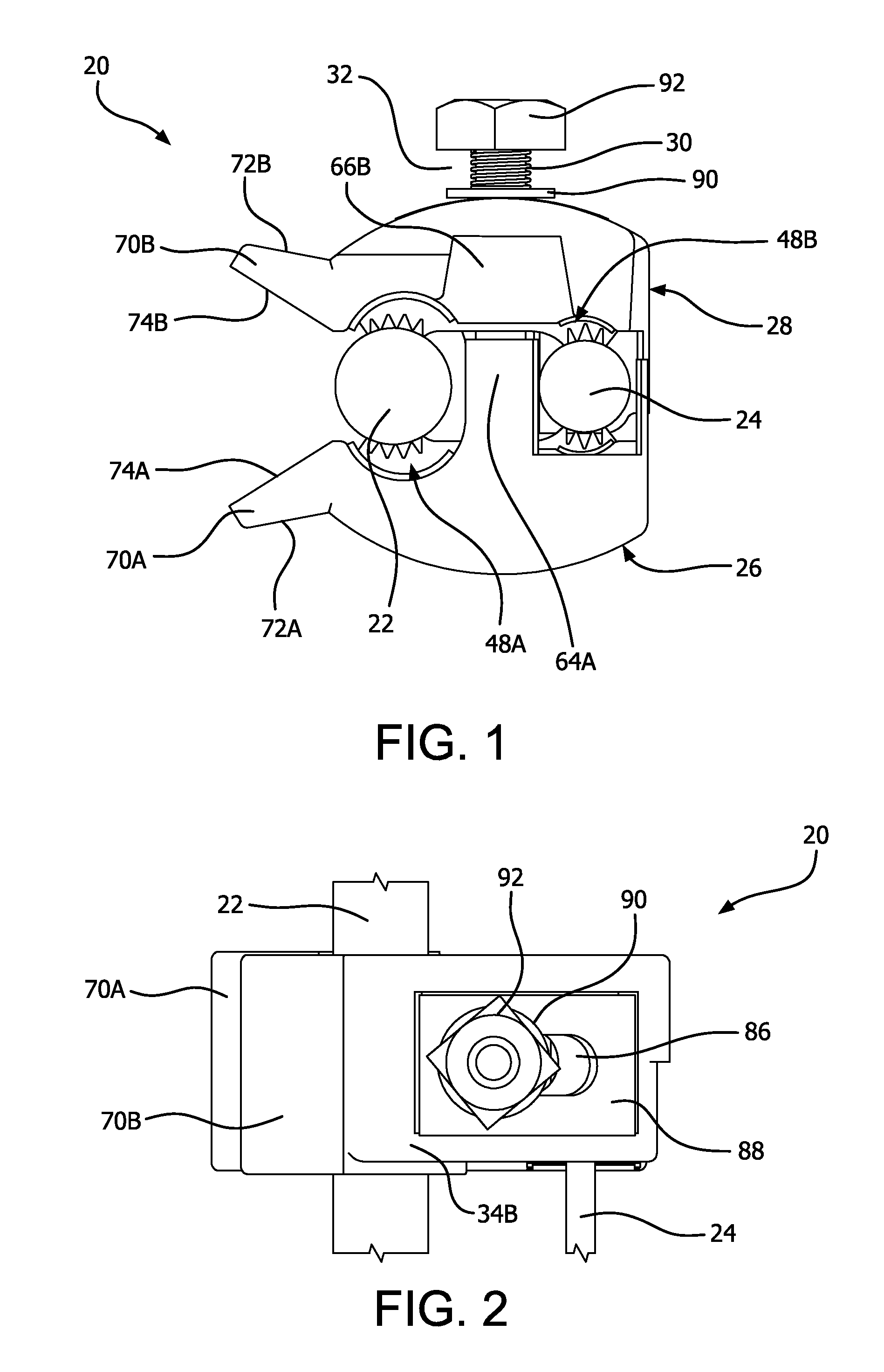
[0025]The drawings depict an exemplary electrical connector 20 to connect a first conductor 22, for example a main or run conductor with a second conductor 24, for example a tap conductor. The electrical connector 20 is a spring loaded electrical connector similar to that described in U.S. Pat. No. 7,666,024, the disclosure of which is hereby incorporated by reference in order provide greater detail or to describe additional aspects, but is in no way meant to limit or contradict the disclosure set forth herein. Although the exemplary embodiments of the present invention are described with regard to electrically connecting a tap conductor to a run conductor of an overhead power distribution system, the present invention is equally applicable to electrically connecting any two conductors. It should be understood that any combination of conductor types or sizes may be accommodated.

[0026]FIGS. 1 and 2 depict the electrical connector 20 receiving a first conductor 22 and a second conduct...


PUM


Abstract

An electrical connector includes first and second pads. The first pad includes first and second grooves and the second pad includes third fourth grooves. A first insulation displacing contact extends from the first groove to the second groove. A second insulation displacing contact extends from the third groove to the fourth groove. The first and second pads are connected by a mechanical fastener. When the first and second pads are connected the first groove aligns with the third groove and the second groove aligns with the fourth groove.

Description

FIELD OF THE INVENTION[0001]The present invention relates generally to a spring-loaded electrical connector for electrically connecting various diameter first and second conductors.BACKGROUND OF THE INVENTION[0002]A power line clamp connector is used to make a permanent or temporary connection to an overhead power distribution line. For example, U.S. Pat. No. 3,075,166 to Peek discloses a conventional hot line clamp having a threaded eye bolt for adjusting a clamping member. One disadvantage associated with conventional power line clamp connectors is that complex maneuvering of a utility lineman's hot stick is required to manipulate an eyebolt of the clamp to connect to the conductors. As maintenance and installation operations become increasingly difficult, the added time required for these operations can increase operating costs for the utility company.[0003]Parallel cable clamps are configured to electrically connect a main conductor to a tap conductor running parallel to the mai...

Claims


Application Information

Patent Timeline
Patent Type & Authority Applications(United States)
IPC IPC(8): H01R4/24H01R43/16
CPCH01R43/16H01R4/2404H01R4/2408H01R43/01
Inventor MARTIN, EVAN
Owner HUBBELL INC
Why Eureka
Try Eureka