Occlusive Device

a technology of occlusive devices and aneurysms, applied in the field of implants, can solve the problems of primary limitation on the amount of braids, thin walls, and prone to rupturing, and achieve the effect of reducing the migration of components or sections

Active Publication Date: 2016-01-28
TYCO HEALTHCARE GRP LP
View PDF23 Cites 99 Cited by
  • Summary
  • Abstract
  • Description
  • Claims
  • Application Information

AI Technical Summary

Benefits of technology

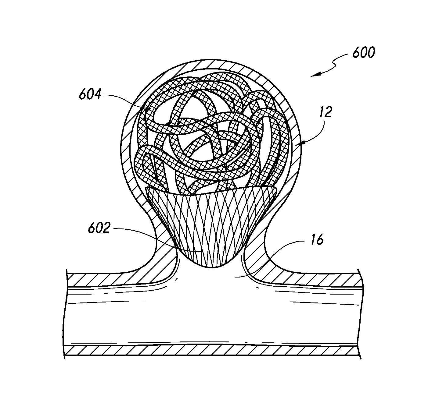
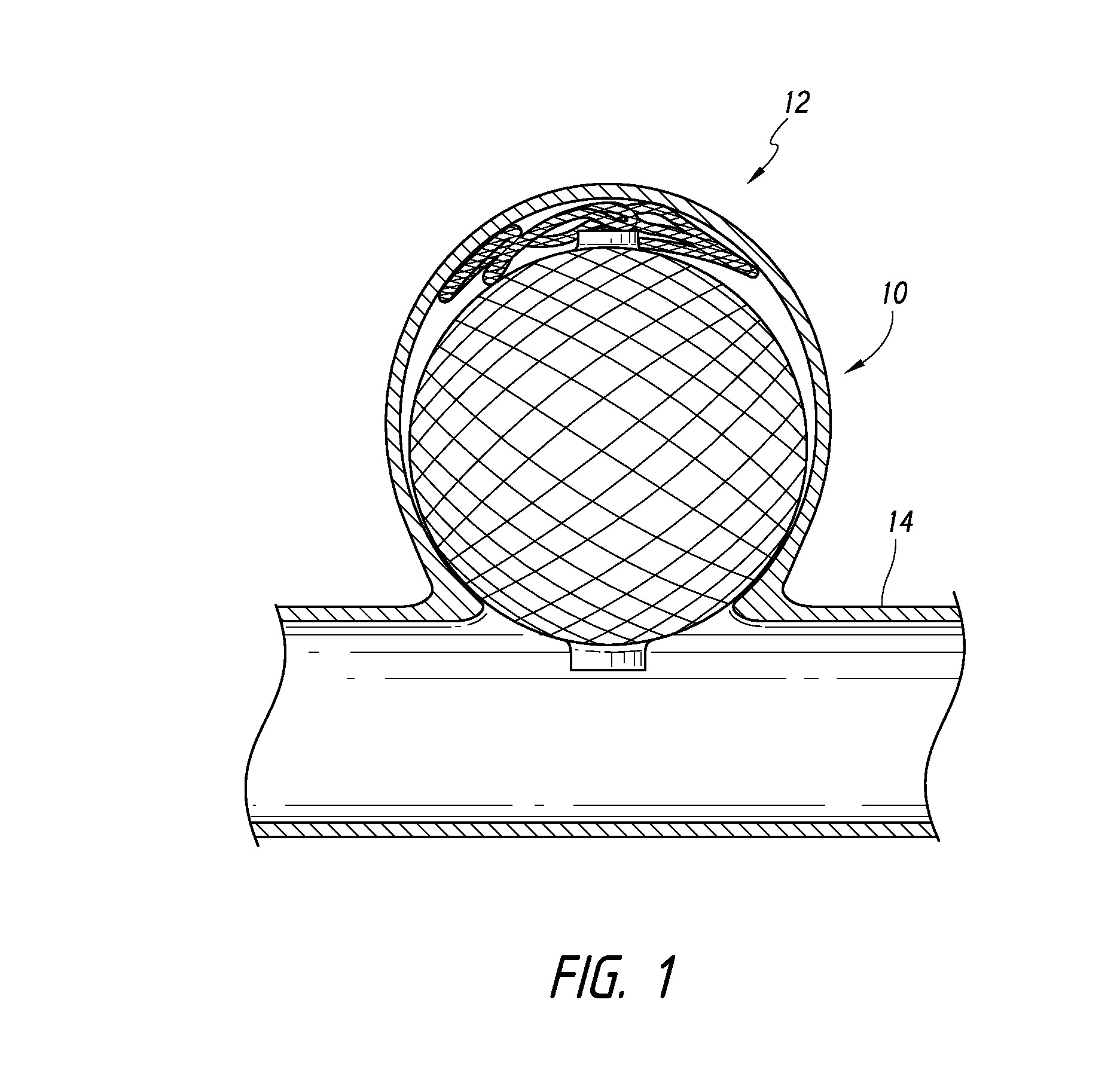
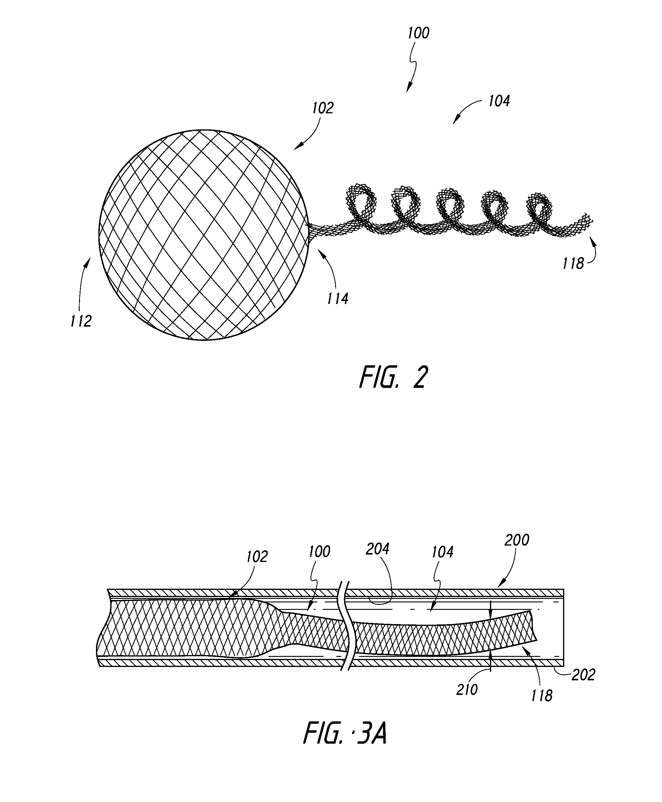
[0011]In accordance with some embodiments, the device can comprise at least two sections formed from a single, continuous piece of material that is shape set such that the sections comprise different shapes or sizes. In some embodiments, a first of the sections can serve a first function and a second of the sections can serve a second function. The first function can include mitigating migration of components or sections of the device, ensuring that the device doesn't pierce the aneurysm wall, providing a frame for the device, or other support or structural functions for device operation. The second function can entail filling the volume of the aneurysm, whether with single or multiple interconnected components. When being placed, the first function can be performed before or after the second function. Accordingly, the first section can be placed into the aneurysm before, after, or concurrently with the second section.
[0012]For example, the first section can function as an atraumatic tip portion that can be placed into an aneurysm before the second portion, providing the second portion a “nest” or cushion when received within the aneurysm. Further, the first section can comprise a framing member into which the second section can be inserted. Accordingly, in some embodiments, the first and second sections can have functions that are interrelated or complimentary. Thus, some embodiments of the device can advantageously integrate multiple components into a device comprising a single, continuous piece of material that provides dynamic and complex functionality.

Problems solved by technology

As is well known, aneurysms have thin, weak walls that are prone to rupturing.
When the weakened wall of an aneurysm ruptures, it can result in death, especially if it is a cerebral aneurysm that ruptures.
The size of microcatheter through which the device can be tracked to achieve endovascular access sets the primary limitation on the amount of braid (i.e., size and number of filaments) that may be included in the device.

Method used


Image

  • Occlusive Device
  • Occlusive Device
  • Occlusive Device

Examples


Embodiment Construction

[0084]In the following detailed description, numerous specific details are set forth to provide a full understanding of the subject technology. It should be understood that the subject technology may be practiced without some of these specific details. In other instances, well-known structures and techniques have not been shown in detail so as not to obscure the subject technology.

[0085]Further, while the present description sets forth specific details of various embodiments, it will be appreciated that the description is illustrative only and should not be construed in any way as limiting. Additionally, it is contemplated that although particular embodiments may be disclosed or shown in the context of aneurysm therapy, such embodiments can be used in other applications for occluding vessels. Furthermore, various applications of such embodiments and modifications thereto, which may occur to those who are skilled in the art, are also encompassed by the general concepts described here...


PUM


Abstract

An aneurysm embolization device can include a body having a single, continuous piece of material that is shape set into a plurality of distinct structural components. For example, the device can have an expandable component and an atraumatic tip portion extending therefrom. Further, the tip portion can be configured to enable the device to be implanted within the aneurysm while tending to mitigate risk of puncturing the aneurysm dome or otherwise assist in framing the aneurysm in advance of placement of additional embolic material.

Description

CROSS-REFERENCE TO RELATED APPLICATIONS[0001]This application claims the priority benefit of U.S. Provisional Application No. 61 / 789,423, filed Mar. 15, 2013, the entirety of which is incorporated herein by reference.BACKGROUND[0002]1. Field of the Inventions[0003]The present inventions relate to implantable devices. More specifically, the present inventions relate to occlusive devices that can be implanted intravenously, and in some embodiments, for aneurysm therapy.[0004]2. Description of the Related Art[0005]Walls of the vasculature, particularly arterial walls, may develop areas of pathological dilatation called aneurysms. As is well known, aneurysms have thin, weak walls that are prone to rupturing. Aneurysms can be the result of the vessel wall being weakened by disease, injury or a congenital abnormality. Aneurysms could be found in different parts of the body with the most common being abdominal aortic aneurysms and brain or cerebral aneurysms in the neurovasculature. When t...

Claims


Application Information

Patent Timeline
Patent Type & Authority Applications(United States)
IPC IPC(8): A61F2/82A61F2/06
CPCA61F2/82A61F2002/823A61F2/06A61B17/12113A61B17/12163A61B17/12172A61B17/12177A61B17/1219A61B2017/00526A61B2017/00867A61B2017/00898
Inventor RUVALCABA, TERESABARDSLEY, EARL FREDERICKRHEE, RICHARD
Owner TYCO HEALTHCARE GRP LP
Why Eureka
Try Eureka