Gas separation membrane module with improved gas seal

a technology of gas seal and separation membrane, which is applied in the direction of membranes, separation processes, manufacturing tools, etc., can solve the problems of increased pressure drop from feed to residue, inefficient operation, and inefficient operation, and achieve the effect of increasing the pressure drop and fasting the performance degradation of downstream membrane elements

Active Publication Date: 2016-01-28
AIR LIQUIDE ADVANCED TECH U S
View PDF19 Cites 16 Cited by
  • Summary
  • Abstract
  • Description
  • Claims
  • Application Information

AI Technical Summary

Benefits of technology

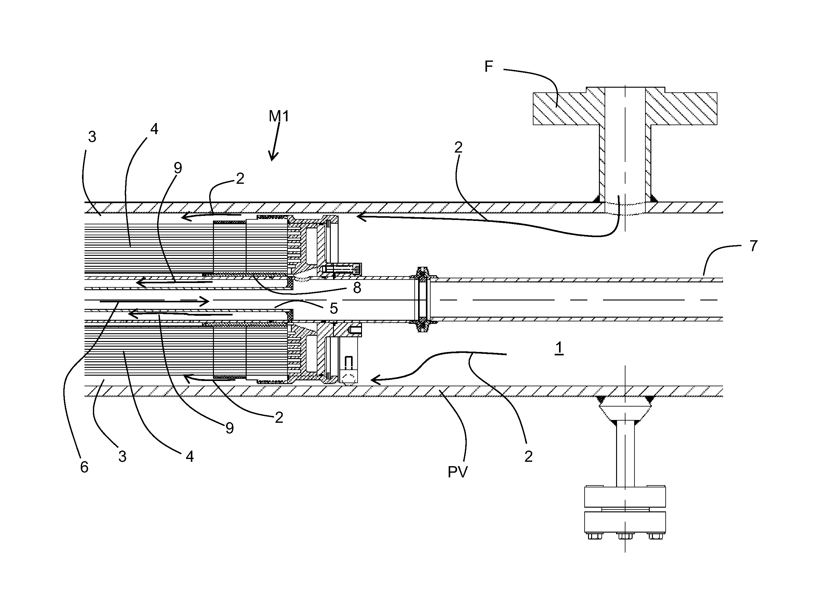
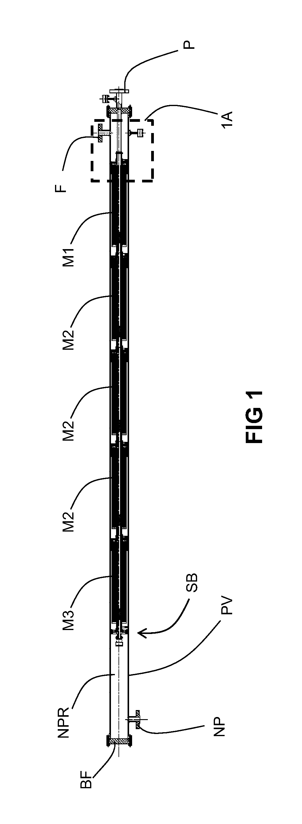
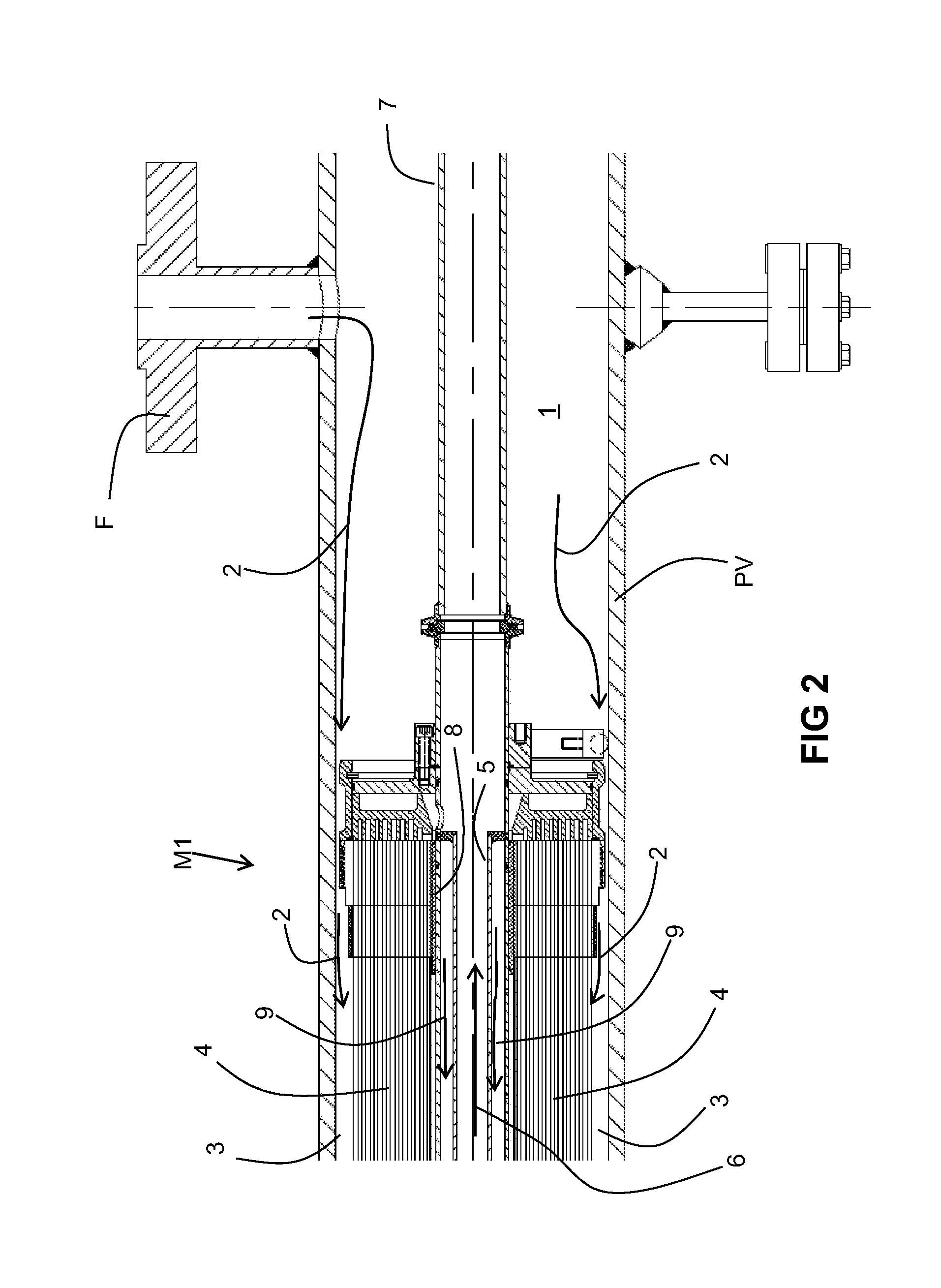
[0019]for each membrane element, each of the associated plurality of fibers has a first end that is open and is encased by a polymeric tubesheet and a second end that is sealed; each of the tubesheets includes a plurality of channels that fluidly communicate with the associated first open fiber ends; and for each tubesheet, the associated plurality of channels fluidly communicate with an associated permeate gas passageway that comprises a pipe extending from an opening in a wall of the outer tube to an opening in a wall of the inner tube, the permeate gas passageways being leak-tight in that non-permeate gas in the outer tube is prevented from leaking into the inner tube at the passageways.

Problems solved by technology

This leads to inefficient operation.
Similar to U.S. Pat. No. 5,851,267, the membrane arrangement disclosed by U.S. Pat. No. 7,338,601 also exhibits faster performance degradation of the downstream membrane elements in comparison to the upstream membrane elements (in the context of the direction of the flow of feed gas), leading to inefficient operation.
It also results in a greater pressure drop from the feed to residue (also known as retentate or non-permeate).

Method used


Image

  • Gas separation membrane module with improved gas seal
  • Gas separation membrane module with improved gas seal
  • Gas separation membrane module with improved gas seal

Examples


examples

[0125]A cylindrical test chamber (having an internal diameter of 8.274 inches) emulating the inner surface of a typical pressure vessel was utilized for pressure-testing sealing bodies. Each of two different sealing bodies was configured as shown for the sealing SB in FIG. 8. The only difference between the two sealing bodies was their diameter. Two types of o-rings (obtained from McMaster Carr and made of acrylonitrile butadiene rubber) were tested, each having a different hardness. In each case, the cup seal (obtained from Parker and made of cross-lined acrylonitrile butadiene rubber) was the same. In some cases, the pressure and / or time duration was varied. Using only human force, attempts were made to push the sealing body into the interior of the test chamber. The sealing body's ability to provide a gas-tight seal without leaks was then observed. The data is shown below in Table I.

TABLE IResults of Pressure-Testing of Sealing BodiesO-ringSealingAp-Shorebodypliedhardness,outerpr...


PUM

PropertyMeasurementUnit
pressureaaaaaaaaaa
pressureaaaaaaaaaa
pressureaaaaaaaaaa

Abstract

Parallel membrane elements are arranged in parallel within a pressure vessel. A sealing body is disposed within the pressure vessel and is compressed against an inner surface of the pressure vessel to provide a leak-right seal in between a feed gas side of the sealing body and a non-permeate side of the sealing body. The sealing body may be slid within the pressure vessel without damaging the sealing body and in all cases without requiring mechanical assistance.

Description

CROSS-REFERENCE TO RELATED APPLICATIONS[0001]None.BACKGROUND[0002]1. Field of the Invention[0003]The present invention relates to gas separation membranes.[0004]2. Related Art[0005]Membranes are commonly used for large scale fluid (water or gas) separation processes. Gas separation membranes are commonly manufactured in one of two configurations: flat sheet or hollow fiber. The flat sheets are typically combined into a spiral wound element. On the other hand, the hollow fibers are commonly bundled together in a manner similar to a shell and tube heat exchange or they are wrapped around a mandrel.[0006]In typical spiral wound flat sheet membranes, two flat sheets of membrane with a permeate spacer in between are joined, for example glued, along three of their sides to form an envelope (i.e., a “leaf”) that is closed on three sides but open on one side. These envelopes are separated by feed spacers and wrapped around or otherwise to form a perforated permeate tube with the open side o...

Claims


Application Information

Patent Timeline
Patent Type & Authority Applications(United States)
IPC IPC(8): B01D65/00B01D63/02B01D67/00
CPCB01D63/02B01D65/003B01D2313/04B01D2319/04B01D67/0086B01D2256/245B01D2257/504B01D2053/224B01D53/22B01D53/226B01D63/043B01D2313/105B01D2313/125B01D2313/13B01D2319/022Y02C20/40B01D53/227B01D63/10
Inventor KARODE, SANDEEP K.BEERS, KARL S.
Owner AIR LIQUIDE ADVANCED TECH U S
Why Eureka
Try Eureka