Belt tensioning motor mount

Inactive Publication Date: 2016-01-28
MILLER CHRISTOPHER B
View PDF36 Cites 4 Cited by
  • Summary
  • Abstract
  • Description
  • Claims
  • Application Information

AI Technical Summary

Benefits of technology

The invention is a device that adjusts the tension of a belt by sliding a motor mount along a support plate. A groove on the support plate makes it easy to slide the motor mount. By moving the driver pulley away from the return pulley, the tightness of the belt is increased. The device uses a threaded bolt that pushes the motor mount along the groove to tighten the belt when turned in one direction, or reduces the tension when turned in the other direction. This allows for very precise adjustments of the belt tension.

Problems solved by technology

Unfortunately, for new construction, the head track often will come into come into contact with the belt tensioning hardware as the house settles, interfering with operation of the doors.

Method used


Image

  • Belt tensioning motor mount
  • Belt tensioning motor mount
  • Belt tensioning motor mount

Examples


Embodiment Construction

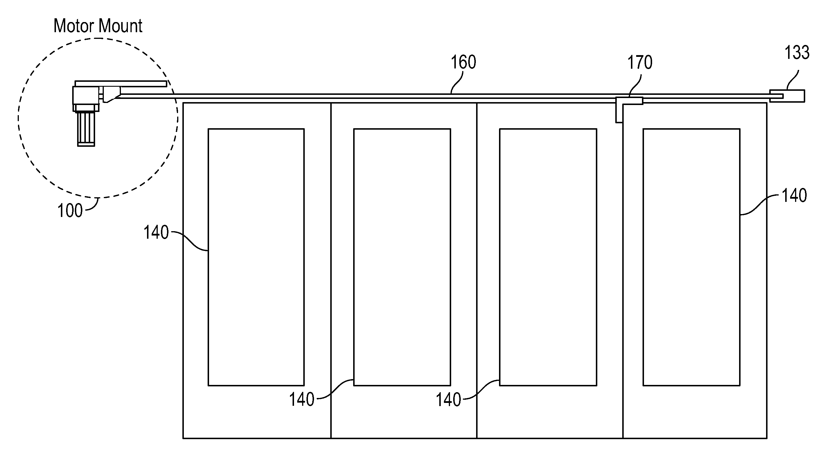
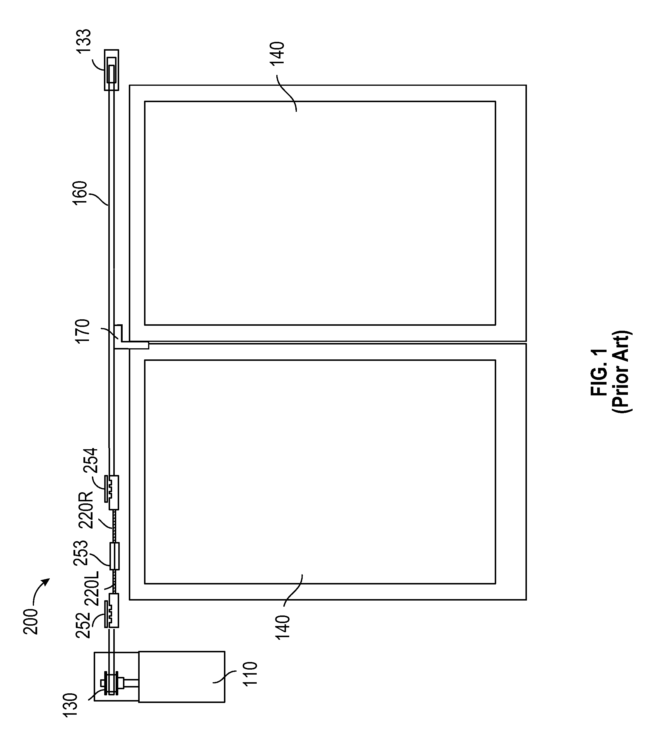
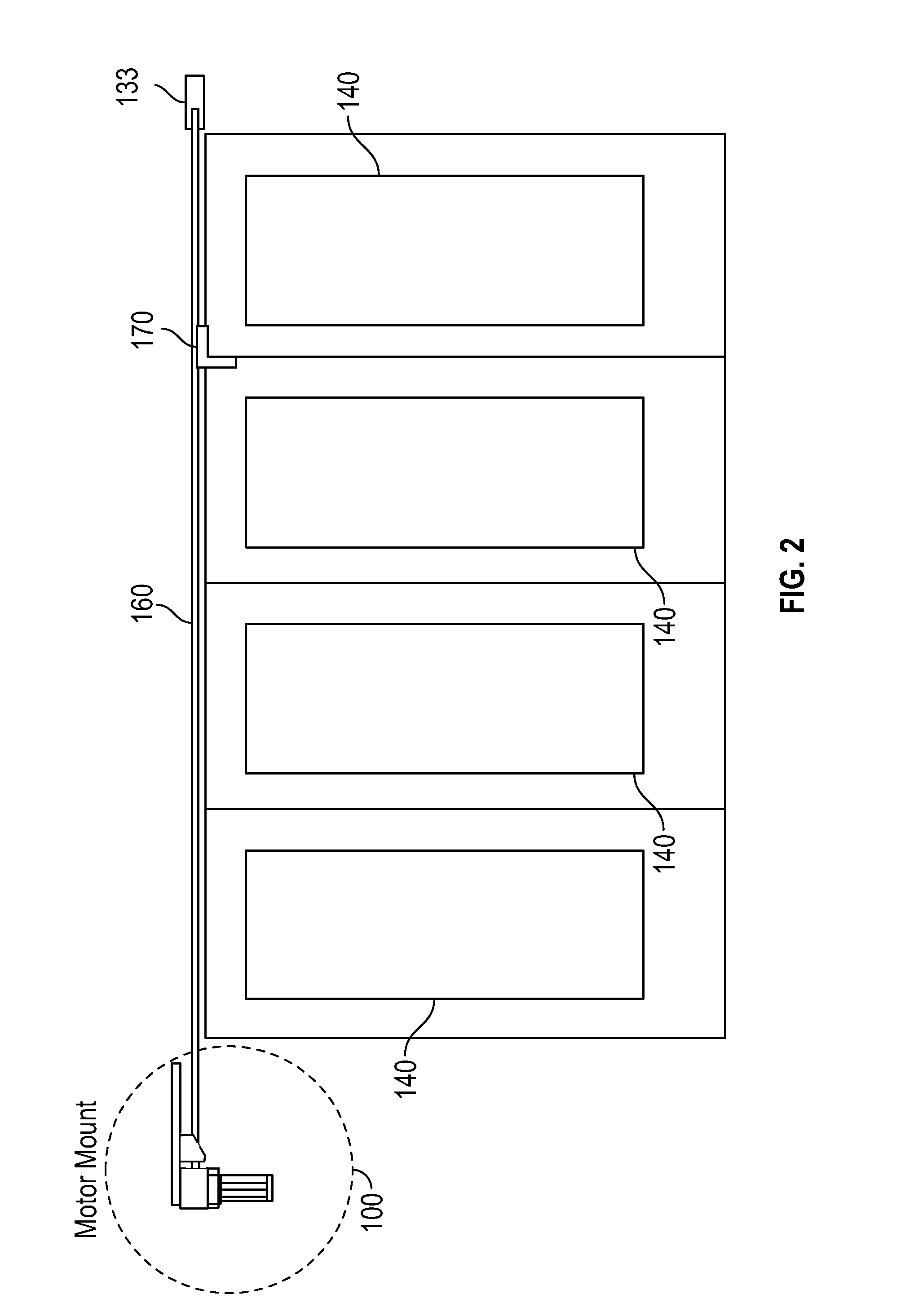
[0013]Referring to FIG. 1, a motorized sliding door system having a prior art belt tensioning device 200, is illustrated. The motorized sliding door system includes a plurality of sliding doors 140. Although not shown, it is to be understood that the sliding doors 140 may be hung from head tracks and include rollers that allow the doors 140 to travel along the tracks. A bi-directional electric motor 110 is mounted on one side of the sliding doors 140. A driver pulley 130 is attached to the shaft of the motor 110 and a return pulley 133 is installed on the opposite side. A belt 160 is attached to the pulleys 130, 133. The belt 160 includes a belt clamp 170 attached to at least one of the doors 140. When the motor 110 is activated, the belt 160 moves along the pulleys 130, 233 and the belt clamp 170 moves the doors 140.

[0014]However, because the belt 160 can become loose over time, the belt 160 must be periodically tightened. As shown, the belt tensioning device 200 is interdisposed b...


PUM


Abstract

A belt tensioning motor mount comprises a support plate; a motor mount holding a motor, the motor mount slidably attached to the support plate; and a tension adjustor disposed on the support plate, the tension adjustor for adjusting the position of the motor mount along the support plate. In an embodiment, the motor mount includes an opening that accommodates a shaft of the motor, a driver pulley attached to the shaft. A belt is attached to the driver pulley on one side and a return pulley on an opposite side. The support plate is disposed adjacent a wall and above the belt which operates a plurality of sliding doors. In an embodiment, the tension adjustor includes a threaded bolt which, depending on which way turned, either causes the motor mount to slide in a first direction to increase belt tension or slide in a second direction to decrease belt tension.

Description

CROSS-REFERENCE TO RELATED APPLICATIONS[0001]This application claims priority of provisional application Ser. No. 61 / 999,416 to Christopher B. Miller, entitled “BELT TENSIONING MOTOR MOUNT FOR RESIDENTIAL SLIDING DOOR AUTOMATION,” filed on Jul. 24, 2014, the subject matter of which is incorporated herein by reference.BACKGROUND OF THE INVENTION[0002]1. Field of the Invention[0003]The present invention relates to belt tensioning devices, and, more particularly, to a belt tensioning motor mount for motorized sliding doors.[0004]2. Description of the Related Art[0005]Automatic motorized sliding door systems have become increasingly popular in residential construction, particularly in high-end and custom-built homes. Motorized sliding doors are typically hung from head tracks and include rollers that allow the doors to travel along the tracks. In many cases, the doors are mounted in a metal frame with tracks and rollers overhead and on the floor. A bi-directional electric motor is mount...

Claims


Application Information

Patent Timeline
IPC IPC(8): E05F15/643F16H7/14E06B3/46F16H7/02
CPCE05F15/643F16H7/02F16H7/14E06B3/4636F16H2007/0842E05Y2201/43E05Y2201/672E05Y2600/626E05Y2900/132F16H2007/0802
Inventor MILLER, CHRISTOPHER B.
Owner MILLER CHRISTOPHER B
Why Eureka
Try Eureka