Cutter assembly having a limiting structure

a cutting assembly and limiting structure technology, applied in the direction of thrusting weapons, white arms/cold weapons, weapons, etc., can solve the problems of easy vibration at the distal end of the blade, and the inability of conventional cutter assemblies to apply fine cutting processes stably and accurately, so as to improve the operation stability of the blade

Inactive Publication Date: 2016-02-04
SDI CORPORATION
View PDF26 Cites 9 Cited by
  • Summary
  • Abstract
  • Description
  • Claims
  • Application Information

AI Technical Summary

Benefits of technology

[0007]The main objective of the invention is to provide a cutter assembly having a limiting structure to prevent an offset of a blade so as to improve the operation stability of the blade.

Problems solved by technology

However, the blade is connected with the slider at one end of the blade, while the other part of the blade is not connected to the blade holder or other components of the cutter assembly.
Vibration at the distal end of the blade easily occurs, such that the conventional cutter assembly cannot be applied to a fine cutting process stably and accurately.

Method used


Image

  • Cutter assembly having a limiting structure
  • Cutter assembly having a limiting structure
  • Cutter assembly having a limiting structure

Examples


Embodiment Construction

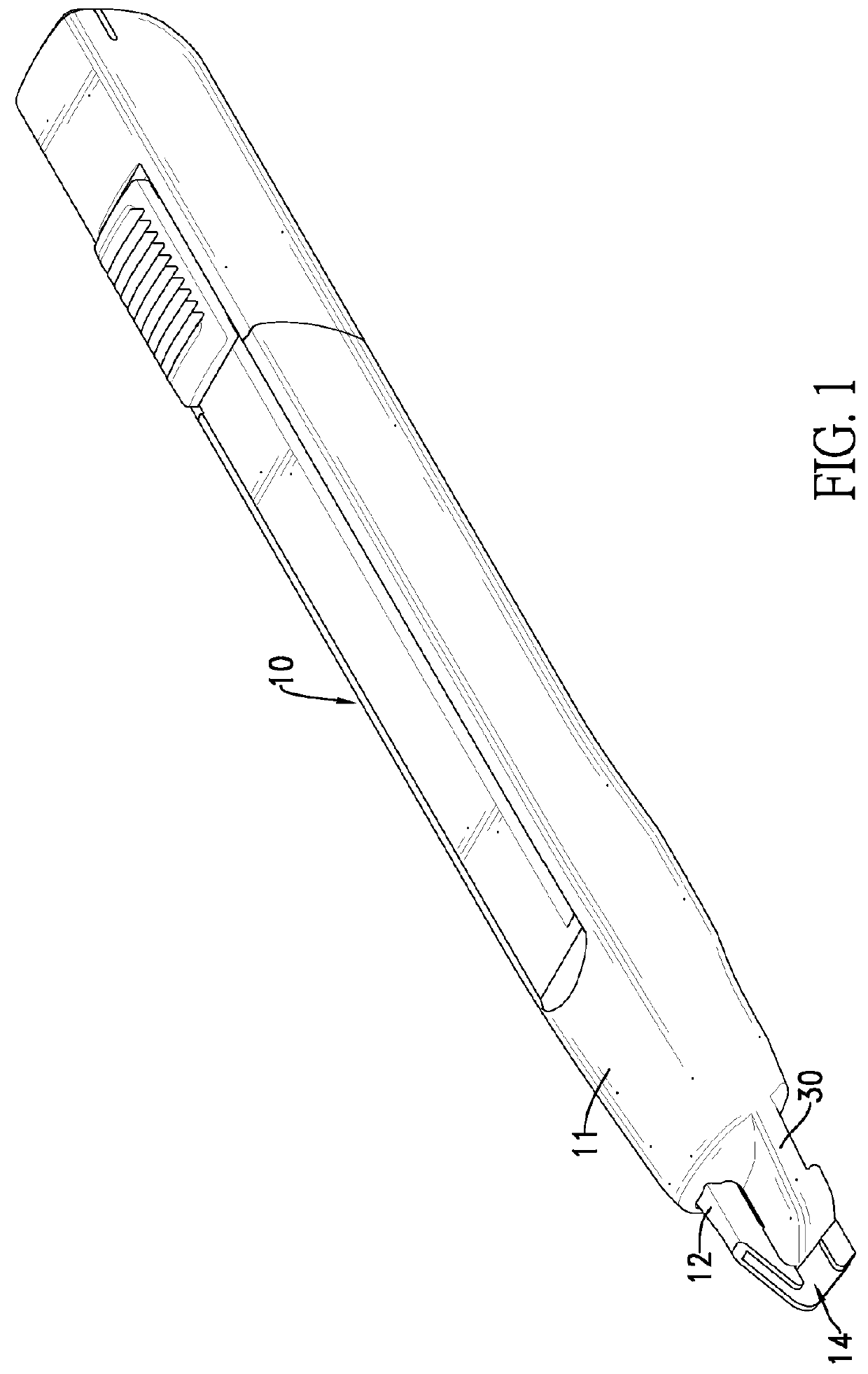
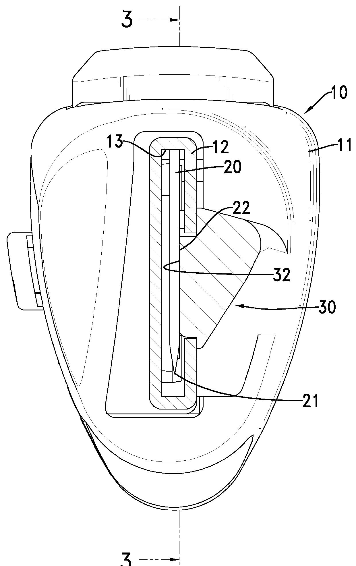
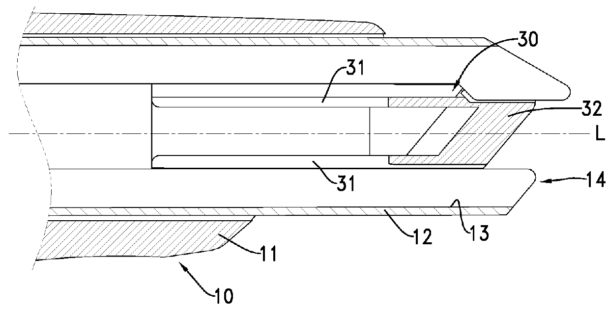
[0020]With reference to FIGS. 1 to 4, a first embodiment of a cutter assembly in accordance with the present invention comprises a blade holder 10, a blade 20 and a limiting element 30.

[0021]The blade holder 10 comprises a holder body 11 and a blade base 12. The holder body 11 has a first end and a second end. The blade base 12 is mounted in and through the holder body 11 and has an end protruding from the first end of the holder body 11. An opening 14 is defined in the end of the blade base 12 and is adjacent to the first end of the holder body 11. An elongated blade chamber 13 is defined in the holder body 11 and the blade base 12 and extends along a longitudinal direction L of the blade holder 10. The blade chamber 13 communicates with the opening 14. In a preferred embodiment, the blade base 12 is made of metal. The blade 20 is moveably mounted in the blade chamber 13 and has a cutting edge 21 formed on a bottom of the blade 20 and a distal end adjacent to the opening 14.

[0022]T...


PUM


Abstract

A cutter assembly has a blade holder, a blade and a limiting element. The blade holder has an elongated blade chamber defined along a longitudinal direction of the blade holder and an opening defined in one end of the blade holder and communicating with the blade chamber. The blade is moveably mounted in the blade chamber. The limiting element is mounted on the blade holder at a position adjacent to the opening and has a limiting segment extending into the blade chamber and abutting a side surface of the blade.

Description

BACKGROUND OF THE INVENTION[0001]1. Field of the Invention[0002]The present invention relates to a cutter assembly, and more particularly to a cutter assembly having a limiting structure to prevent an offset of a blade.[0003]2. Description of Related Art[0004]A retractable cutter substantially comprises a blade holder, a blade and a slider. The slider is mounted moveably on the blade holder. The blade is mounted slidably in the blade holder and is connected to the slider. When the slider is pushed, the blade is moved relative to the blade holder to extend out of or to retract into the blade holder.[0005]However, the blade is connected with the slider at one end of the blade, while the other part of the blade is not connected to the blade holder or other components of the cutter assembly. Therefore, offset of the blade easily occurs during the operation of the cutter assembly, particularly at a distal end of the blade opposite to the slider. The distal end of the blade is most away f...

Claims


Application Information

Patent Timeline
Patent Type & Authority Applications(United States)
IPC IPC(8): B26B1/08B26B5/00
CPCB26B1/08B26B5/006B26B5/002
Inventor WU, CHIEN-LUNG
Owner SDI CORPORATION
Why Eureka
Try Eureka