USB connector positioning structure

a positioning structure and usb connector technology, applied in the direction of coupling parts engagement/disengagement, coupling device connection, electrical apparatus, etc., can solve the problems of insufficient positioning holes at the standard a-plug of the male usb connector, insufficient supply, user's personal data can easily be stolen or broken, etc., to achieve the effect of improving the operational stability of the installed male usb connector

Active Publication Date: 2015-01-06
ADLINK TECH INC
View PDF8 Cites 10 Cited by
  • Summary
  • Abstract
  • Description
  • Claims
  • Application Information

AI Technical Summary

Benefits of technology

[0008]The present invention has been accomplished under the circumstances in view. It is one object of the present invention to provide a USB connector positioning structure, which comprises a protective casing mountable at a frame shell of a machine case around a USB connector insertion slot for guiding insertion of a male USB connector through the USB connector insertion slot into a plug hole in a female USB connector at a circuit board inside the machine case, and a positioning holder shell coupled to the protective casing for holding the inserted male USB connector in place. The protective casing comprises a horizontal top panel, two vertical side panels respectively downwardly extended from two opposite lateral sides of the horizontal top panel and defining with said horizontal top panel a forwardly extending bottom open space having opposing front and rear openings, two sliding guides respectively located in the vertical side panels, and two mounting lugs respectively perpendicularly extended from a rear end of each of the two vertical side panels at right angle in opposite direction for mounting. The positioning holder shell comprises a horizontal bottom panel, two upright side panels respectively located at two opposite lateral sides of the horizontal bottom panel, an upright front panel located at a front side of the horizontal bottom panel and defining with the horizontal bottom panel and the two upright side panels a backwardly extending top open space in match with the forwardly extending bottom open space of the protective casing, two coupling members respectively located at the upright side panels outside the backwardly extending top open space and respectively coupled to the sliding guides to secure the positioning holder shell to the protective casing, allowing the positioning holder shell to be moved forward and backward relative to the protective casing between an open condition and a close position. Thus, the positioning holder shell can prohibit the male USB connector from a backward displacement or accidental falling due to an external vibration force, protects the installed male USB connector against accidental damage, and enhances the operational stability of the installed male USB connector.

Problems solved by technology

However, when finding data on the internet, the user's personal data can easily be stolen or broken by a hiker, or computer virus may enter the user's computer system through an attachment to an e-mail.
However, the limited contact area between the spring leaves of the mating female USB connector and the locating holes at the standard A-plug of the male USB connector is insufficient to keep the inserted male USB connector constantly and accurately in position.
Further, the motherboard or interface. circuit board does not provide any support means around the mating female USB connector to support the inserted male USB connector in position.
If the male USB connector is vibrated accidentally by an external force, or the user plugs or unplugs an interface card or bus line in the computer system, or the computer system is under an environment of low level of reliability, the inserted male USA connector may be loosened and electrically disconnected from the mating female USB connector, causing damage or losing its function.

Method used


Image

  • USB connector positioning structure
  • USB connector positioning structure
  • USB connector positioning structure

Examples


Embodiment Construction

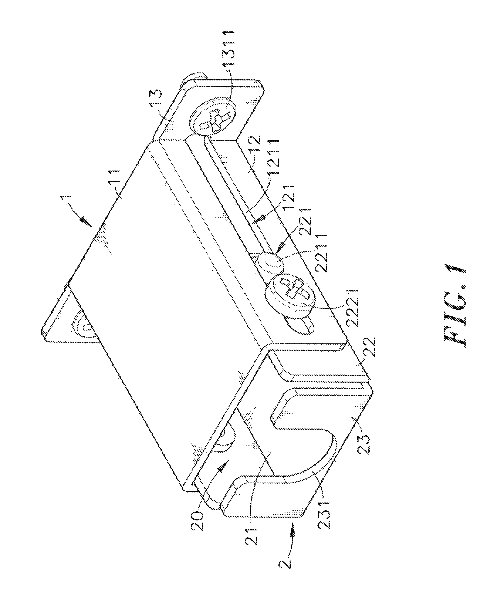
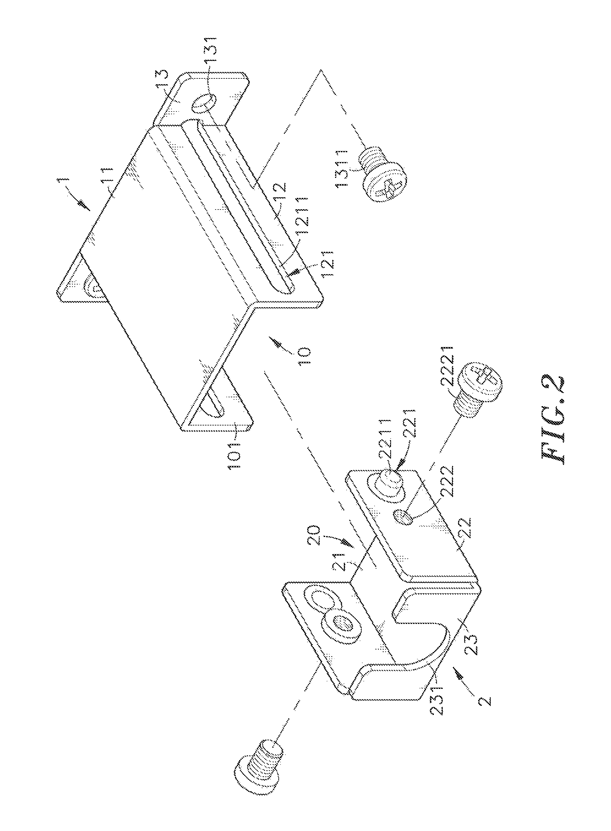
[0021]Referring to FIGS. 1-5, a USB connector positioning structure in accordance with the present invention is shown. As illustrated, the USB connector positioning structure comprises a protective casing 1, and a positioning holder shell 2.

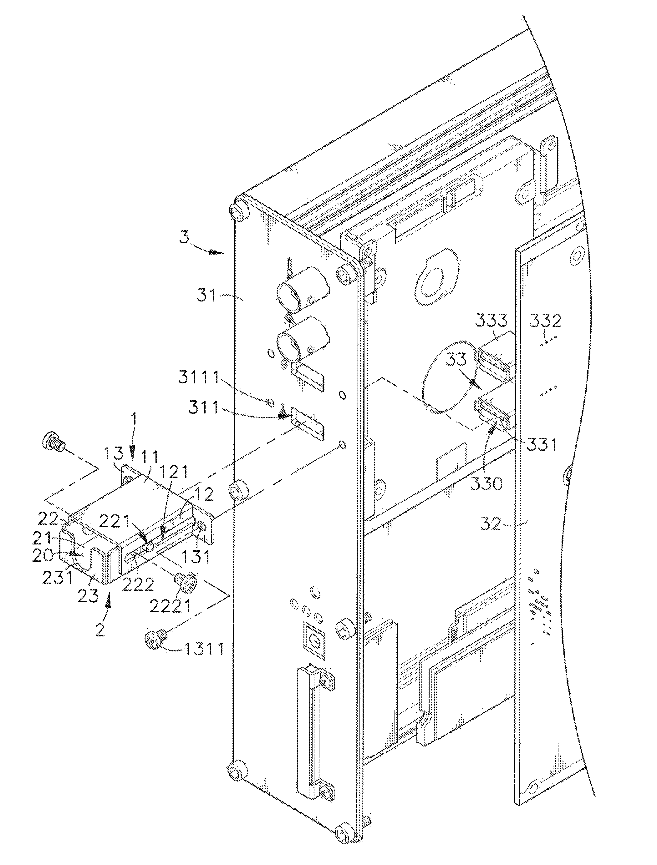
[0022]The protective casing I comprises a horizontal top panel 11, two vertical side panels 12 respectively downwardly extended from two opposite lateral sides of the horizontal top panel 11 and defining with the horizontal top panel 11 a forwardly extending bottom open space 10 having opposing front and rear openings 101, a sliding guide 121, for example, sliding slot 1211 located in each vertical side panel 12, two mounting lugs 13 respectively perpendicularly extended from the rear end of each of the two vertical side panels 12 at right angle in opposite direction, and a mounting through hole 131 located on each mounting lug 13 for the mounting of one respective mounting screw 1311 to affix the protective casing 1 to a machine ease 3.

[0023]The...


PUM


Abstract

A USB connector positioning structure includes a protective casing affixed to a frame shell of a machine case around a USB connector insertion slot for guiding insertion of a male USB connector through the USB connector insertion slot into a plug hole in a female USB connector at a circuit board inside the machine case, and a positioning holder shell pivotally coupled to the protective casing and biasable between a close horizontal position and an opened vertical position and movable along two horizontal guide slots of the protective casing for holding an inserted male USB connector in connection with the female USB connector in the machine case and protecting the inserted male USB connector against external pressure, and holding screws for locking the protective casing and the inserted gale USB connector in position.

Description

BACKGROUND OF THE INVENTION[0001]1. Field of the Invention[0002]The present invention relates to Universal Serial Bus (USB) connector positioning technology and more particularly, to a USB connector positioning structure, which comprises a protective casing mountable at a frame shell of a machine case around a USB connector insertion slot for guiding insertion of a male USB connector through the USB connector insertion slot into a plug hole in a female USB connector at a circuit board inside the machine case, and a positioning holder shell coupled to the protective casing for holding the inserted male USB connector in place, prohibiting the male USB connector from a backward displacement or accidental falling due to an external vibration force, protecting the installed male USB connector against accidental damage, and enhancing the operational stability of the installed male USB connector.[0003]2. Description of the Related Art[0004]Following fast development of computer electronic ...

Claims


Application Information

Patent Timeline
Patent Type & Authority Patents(United States)
IPC IPC(8): H01R13/62H01R13/629
CPCH01R13/629H01R13/6395H01R13/748
Inventor KUO, JEN-CHIEH
Owner ADLINK TECH INC
Why Eureka
Try Eureka