
Inverting apparatus and control method thereof

a technology of inverting apparatus and control method, which is applied in the direction of electric variable regulation, process and machine control, instruments, etc., can solve the problem of probable tracking error

Active Publication Date: 2015-08-27
SPI ELECTRONICS
View PDF11 Cites 9 Cited by
  • Summary
  • Abstract
  • Description
  • Claims
  • Application Information

AI Technical Summary

Benefits of technology

The invention provides an inverting apparatus and a control method that can avoid misjudgements caused by system noise during maximum power point tracking (MPPT) operation. By determining the variation in power between the disturbed input power and the undisturbed input power, the method ensures that errors in the MPPT operation caused by sampling system noise are avoided. This improves the overall stability of the inverting apparatus and ensures efficient operation.

Problems solved by technology

However, in the existing MPPT operation, if the input power sampled by the control circuit is shifted due to an influence of a system noise or an abnormal operation of the control circuit, when the aforementioned MPPT operation is used to track the maximum power point, a tracking error is probably occurred due to misjudgement caused by the above influence.

Method used


Image

  • Inverting apparatus and control method thereof
  • Inverting apparatus and control method thereof
  • Inverting apparatus and control method thereof

Examples


Embodiment Construction

[0028]Reference will now be made in detail to the present preferred embodiments of the invention, examples of which are illustrated in the accompanying drawings. Wherever possible, the same reference numbers are used in the drawings and the description to refer to the same or like parts.

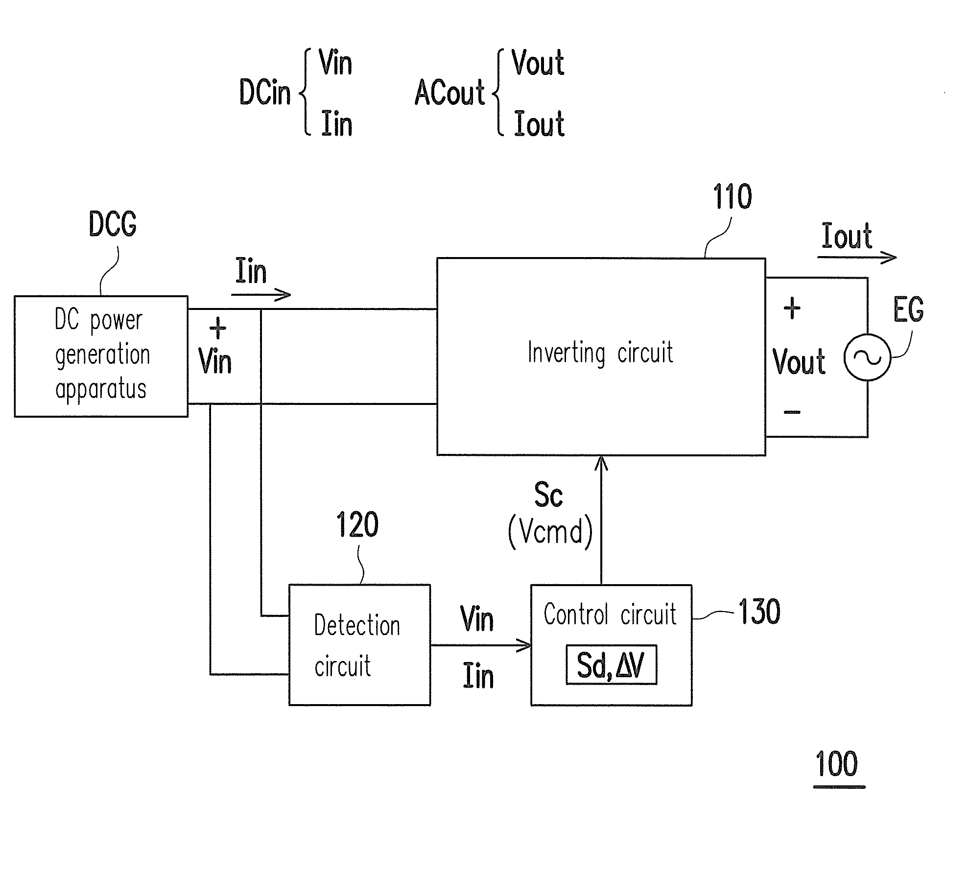
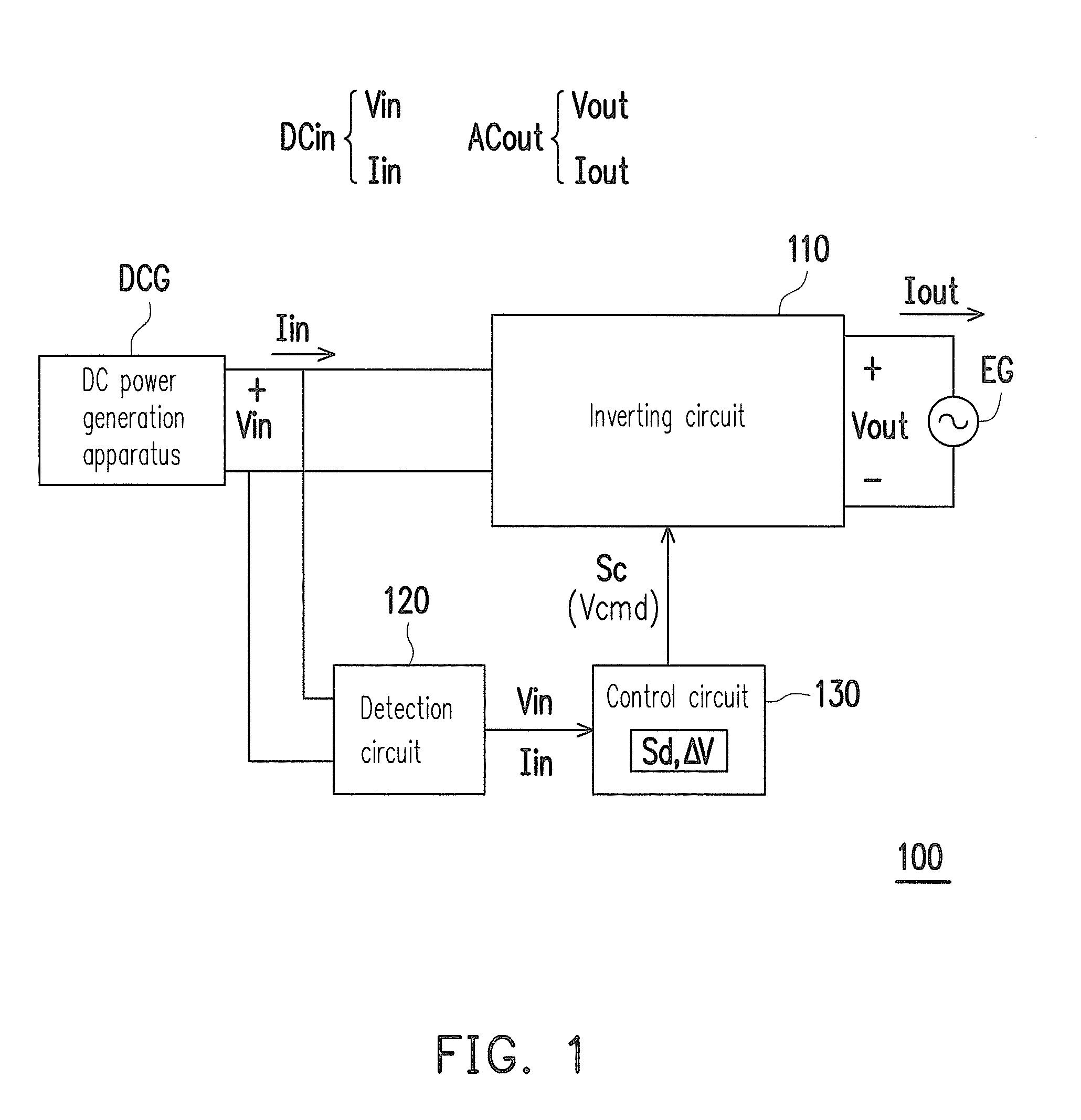
[0029]FIG. 1 is a schematic diagram of an inverting apparatus according to an embodiment of the invention. Referring to FIG. 1, the inverting apparatus 100 of the present embodiment is adapted to an alternating current (AC) power system. In the AC power system, the inverting apparatus 100 receives a direct current (DC) input power DCin (including an input voltage Vin and an input current Iin of the DC type) from a front end DC power generating apparatus DCG, and generates an AC output power ACout (including an output voltage Vout and an output current Iout of the AC type) for providing to a post end electricity grid EG. The DC power generating apparatus DCG is, for example, a photovoltaic module, a w...


PUM


Abstract

An inverting apparatus and a control method thereof are provided. The inverting apparatus includes an inverting circuit, a detection circuit, and a control circuit. The inverting circuit converts a DC input power into an AC output power. The detection circuit detects an input voltage and an input current. The control circuit provides a control signal for disturbing the input voltage, such that a voltage value of the input voltage is adjusted to a command voltage represented by the control signal. The control circuit calculates an input power corresponding to each of time points, calculates a power variation between the disturbed power and the undisturbed power, then determines whether the power variation is larger than a predetermined variation, and sets a disturbance voltage according to the determination result, based on an MPPT operation or based on a disturbance direction of the command voltage of the previous time point.

Description

CROSS-REFERENCE TO RELATED APPLICATION[0001]This application claims the priority benefits of U.S. provisional application Ser. No. 61 / 944,587, filed on Feb. 26, 2014 and Taiwan application serial no. 104104727, filed on Feb. 12, 2015. The entirety of each of the above-mentioned patent applications is hereby incorporated by reference herein and made a part of this specification.BACKGROUND[0002]1. Technical Field[0003]The invention relates to a power conversion technique, and particularly relates to an inverting apparatus and a control method thereof.[0004]2. Related Art[0005]In order to improve a whole conversion efficiency of an inverting apparatus, in the control of the inverting apparatus, a control method of a maximum power point tracking (MPPT) operation is generally used to stably maintain an input power of the inverting apparatus to a maximum power point.[0006]In detail, in the general MPPT operation, a control circuit of the inverting apparatus consecutively samples an input ...

Claims


Application Information

Patent Timeline
IPC IPC(8): H02M7/44G01R21/06
CPCG01R21/06H02M7/44G05F1/67H02M7/48H02J2300/26H02J3/381Y02E10/56
Inventor CHEN, HAN-WEIYU, CHUN-HAOLIU, CHIA-HUA
Owner SPI ELECTRONICS
Learn More