Inner-Rotor Motor

a technology of inner-rotor motor and inner-rotor motor, which is applied in the direction of dynamo-electric machines, magnetic circuit rotating parts, and shape/form/construction of magnetic circuits, etc., can solve the problems of significant reduction of inner-rotor motor safety, adverse effects on and inability to operate normally. to achieve the effect of improving the operational stability of inner-rotor motor

Active Publication Date: 2016-04-14
SUNONWEALTH ELECTRIC MACHINE IND
View PDF10 Cites 10 Cited by
  • Summary
  • Abstract
  • Description
  • Claims
  • Application Information

AI Technical Summary

Benefits of technology

[0009]It is therefore the objective of this invention to provide an inner-rotor motor including an insulating layer arranged between a housing and an iron core of the inner-rotor motor. The insulating layer is adapted to separate the housing and the iron core from each other, thus improving the operational stability of the inner-rotor motor.
[0010]It is another objective of this invention to provide an inner-rotor motor including an insulating layer which achieves the function of electrical isolation between the housing and the iron core. Thus, the electrical conducting path between the housing and the iron core is not formed, and safety of the inner-rotor motor is enhanced.

Problems solved by technology

Since the iron core 912 is adjacent to the housing 911, the conducting wire may easily cause electromagnetic interference to the iron core when electrified.
Thus, noise and vibration are generated during rotation of the inner-rotor motor, and the operational stability of the inner-rotor motor is adversely affected.
Thus, the safety of the inner-rotor motor is significantly reduced.
In light of the above, since the operational stability and safety of the conventional inner-rotor motor are poor, it is necessary to improve such an inner-rotor motor for increasing its market value.

Method used


Image

  • Inner-Rotor Motor
  • Inner-Rotor Motor
  • Inner-Rotor Motor

Examples


first embodiment

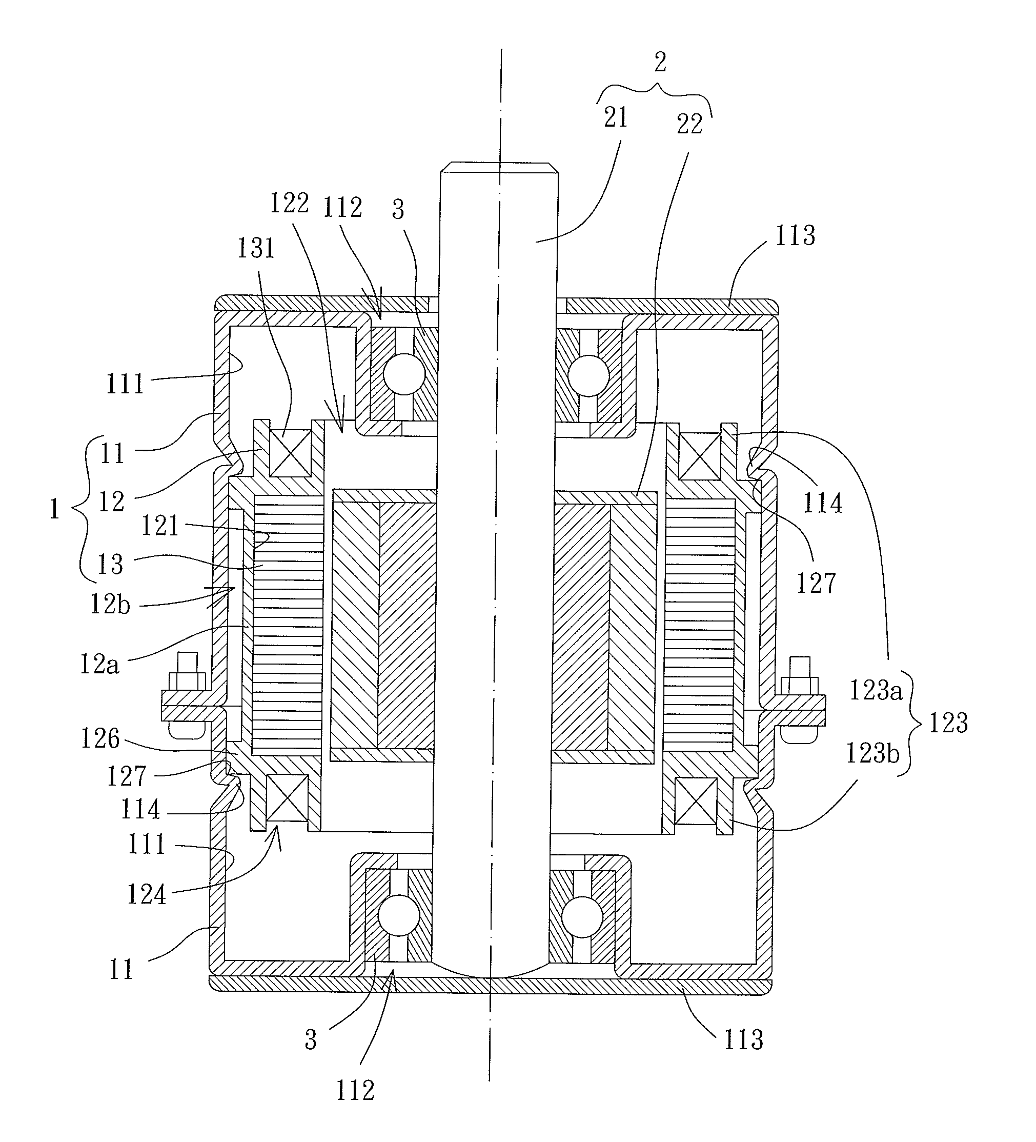
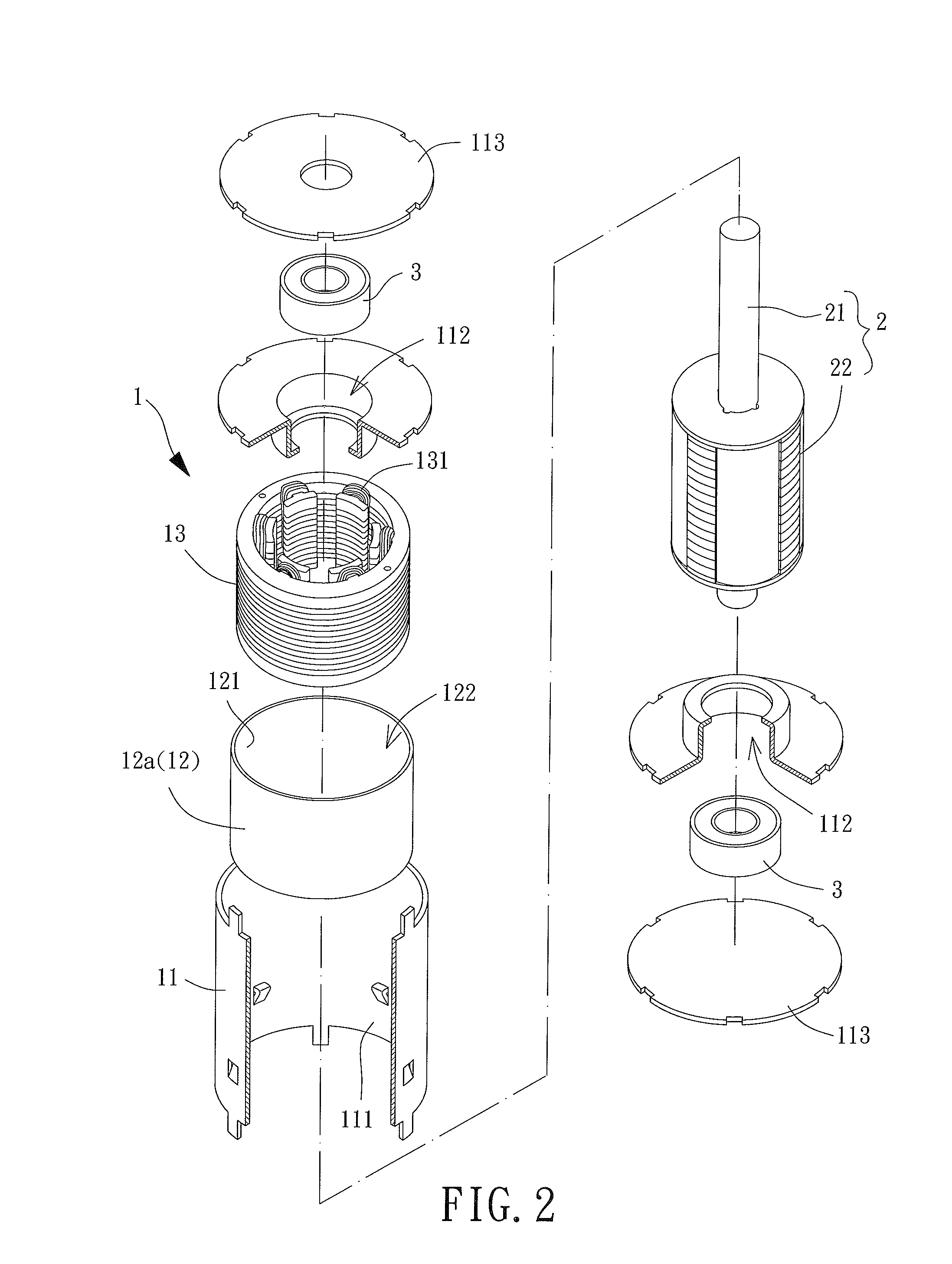
[0039]Please refer to FIGS. 2 and 3, an inner-rotor motor according to the present invention includes a stator 1 and a rotor 2 rotatably coupled to the stator 1.

[0040]The stator 1 includes a housing 11, an insulating layer 12 and an iron core 13. The insulating layer 12 is arranged between the housing 11 and the iron core 13, and the housing 11 is usually made of metal. In this embodiment, the insulating layer 12 includes an insulating member 12a, which is a substantially insulating structure made of an insulating material, such as an insulating sleeve, an insulating cover or an insulating shell. As such, the insulating member 12a may be coupled with the housing 11, and the iron core 13 couples with an inner periphery of the insulating member 12a. The housing 11 includes an inner surface 111 for coupling with the insulating member 12a. The iron core 13 may be coupled to a coupling surface 121 of the insulating member 12a facing away from the housing 11. Specifically, a through hole ...

third embodiment

[0049]Please refer to FIG. 5, an inner-rotor motor according to the present invention also includes a bobbin 123. The inner-rotor motor of this embodiment differs from the two embodiments described above in that the bobbin 123 includes a top bobbin 123a and a bottom bobbin 123b jointly holding the iron core 13 in place from two ends of the iron core 13. Each of the top bobbin 123a and the bottom bobbin 123b may be integrally formed on the insulating layer 12 and may form a recess 124 for positioning the coil 131 on the iron core 13.

[0050]As such, in both the second and third embodiments of the present invention, the insulating layer 12 separates the iron core 13 from the housing 11 along the radial direction of the housing 11. Besides, the insulating layer 12 further includes the bobbin 123 that positions the coil 131 on the iron core 13, thus reducing the production cost of the inner-rotor motor. The top bobbin 123a and the bottom bobbin 123b of the bobbin 123 may be integrally for...

fourth embodiment

[0053]Please refer to FIG. 6, in an inner-rotor motor according to the present invention, the stator 1 also includes a housing 11, an insulating layer 12 and an iron core 13. The insulating layer 12 is radially arranged between the housing 11 and the iron core 13. The inner-rotor motor of this embodiment differs from those embodiments above in that the insulating layer 12 includes an insulating member 12a and an air layer 12b. Specifically, the insulating member 12a is coupled to an inner surface 111 of the housing 11 and includes two ends each being coupled with a connecting portion 126. The connecting portion 126 includes two ends respectively coupled with the insulating member 12a and the iron core 13 and extends along a radial direction of the shaft 21 for separating the insulating member 12a and the iron core 13 from each other. Thus, a gap is formed between the iron core 13 and a coupling surface 121 of the insulating member 12a facing away from the housing 11. The air layer 1...


PUM


Abstract

An inner-rotor motor for preventing the formation of an electrical conducting path between an iron core and a housing of the motor is disclosed in the present invention. The inner-rotor motor includes a stator and a rotor. The stator includes a housing, an insulating layer and an iron core. The insulating layer is arranged between the housing and the iron core and prevents the electrical conducting path from forming between the housing and the iron core. The rotor includes a shaft rotatably coupled with the housing, and a permanent magnet unit arranged around the shaft.

Description

CROSS REFERENCE TO RELATED APPLICATIONS[0001]The application claims the benefit of Taiwan application serial No. 103135244, filed on Oct. 9, 2014, the subject matter of which is incorporated herein by reference.BACKGROUND OF THE INVENTION[0002]1. Field of the Invention[0003]The present invention generally relates to an inner-rotor motor and, more particularly, to an inner-rotor motor which does not form any electrical conducting path between an iron core and a housing of the motor.[0004]2. Description of the Related Art[0005]A cooling fan 9 having a conventional inner-rotor motor is shown in FIG. 1 and includes a stator 91, a rotor 92 and an impeller 93. The stator 91 and the rotor 92 jointly form the conventional inner-rotor motor. The stator 91 includes a housing 911 and an iron core 912 coupled to an inner surface of the housing 911. The rotor 92 includes a shaft 921 and a permanent magnet 922 coupled to an outer circumferential surface of the shaft 921. The rotor 92 is rotatably...

Claims


Application Information

Patent Timeline
Patent Type & Authority Applications(United States)
IPC IPC(8): H02K5/08H02K1/27H02K3/38H02K3/34
CPCH02K5/08H02K3/38H02K1/2706H02K3/345H02K1/185H02K3/522
Inventor HORNG, ALEXYIN, TSO-KUOWANG, CHI-MIN
Owner SUNONWEALTH ELECTRIC MACHINE IND
Why Eureka
Try Eureka