Vibration device, electronic apparatus, and mobile object

Inactive Publication Date: 2016-02-04
SEIKO EPSON CORP
View PDF3 Cites 2 Cited by
  • Summary
  • Abstract
  • Description
  • Claims
  • Application Information

AI Technical Summary

Benefits of technology

The vibration device described in this patent application has several technical effects. Firstly, the vibrating element is connected to multiple support portions on the base substrate, which helps to distribute stress and prevent variations in vibration characteristics. Secondly, the elastic members used to support the vibrating element are connected to the base substrate at separate locations, which further improves stability and reduces the likelihood of spurious vibration characteristics. Thirdly, the elastic members absorb or diffuse the stress caused by changes in temperature, reducing the impact on vibration characteristics. Fourthly, the vibration device can be used in a mobile object, providing more stable and accurate vibration characteristics. Overall, this patent application provides a vibration device with improved stability and efficiency.

Problems solved by technology

In the above-described manner, in a case where the vibrating element is directly fixed, it is hard for stress of the vibrating element caused by a temperature change or the like to be diffused from a fixed portion, and there is a concern that vibration characteristics of the vibrating element may deteriorate due to an influence of the stress.
However, in the above-described cantilevered support configuration in which the area of the fixed portion is reduced, there is a problem in that, in a case where an impact caused by a fall or the like occurs in the vibrating element, since impact stress concentrates on the cantilevered fixed portion, a defect such as deterioration in the connection strength between the vibrating element and the active surface of the integrated circuit chip tends to occur, and it is difficult to reduce the area of the fixed portion.

Method used


Image

  • Vibration device, electronic apparatus, and mobile object
  • Vibration device, electronic apparatus, and mobile object
  • Vibration device, electronic apparatus, and mobile object

Examples


first embodiment

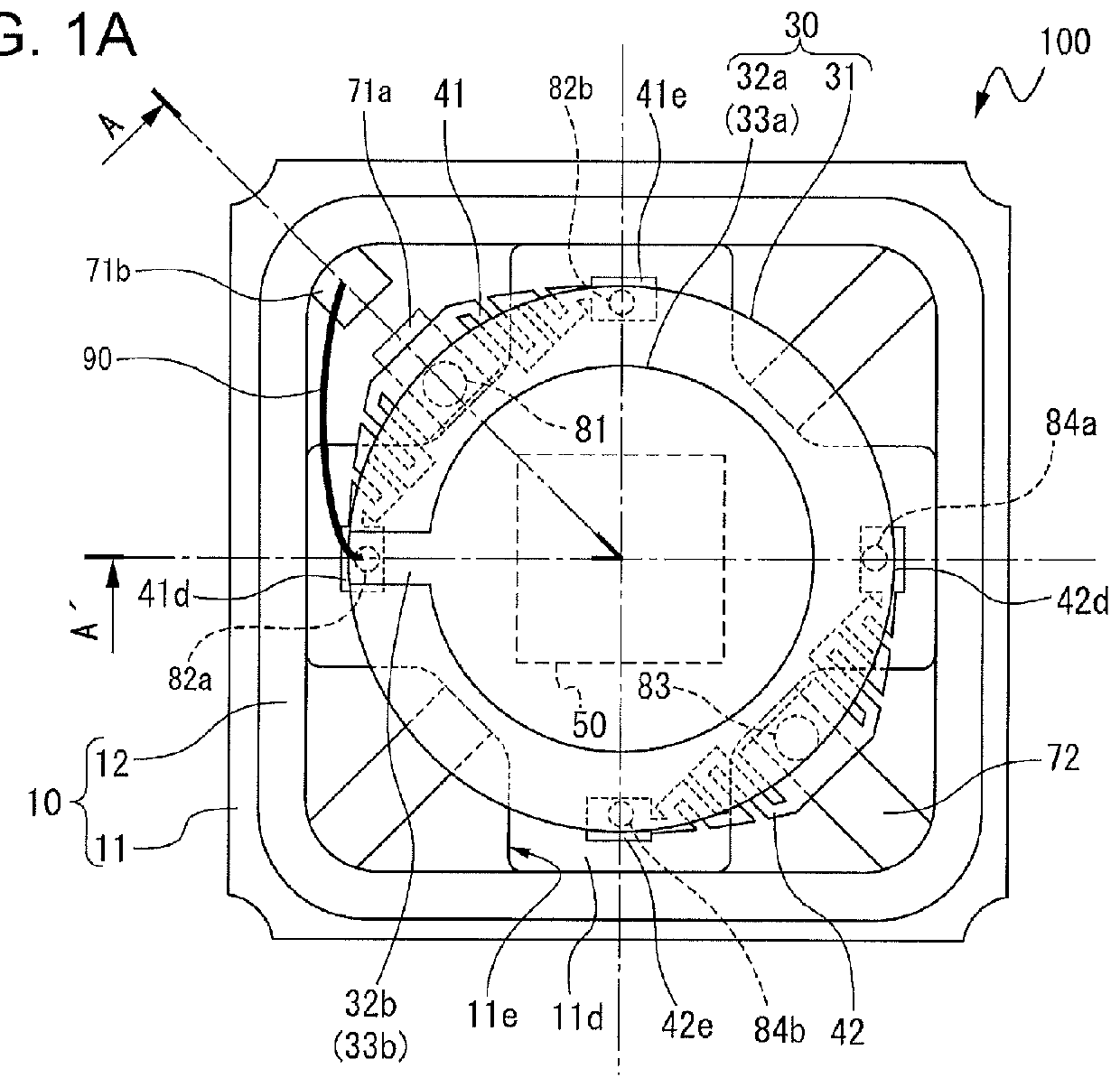
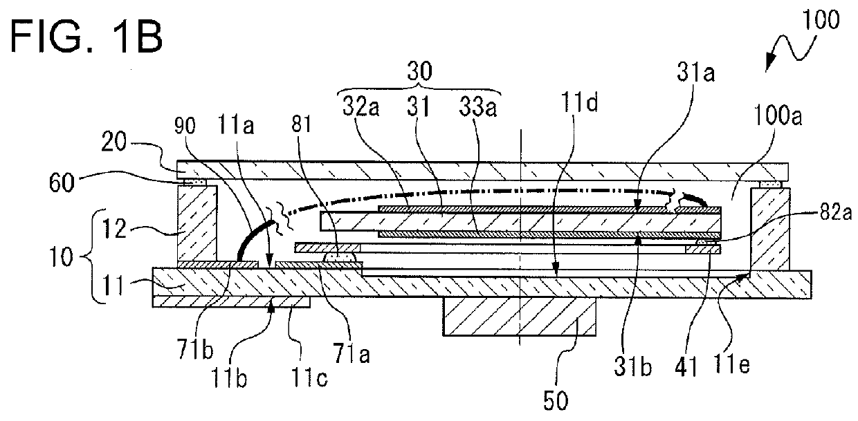
[0043]With reference to FIGS. 1A and 1B, a vibration device according to a first embodiment will be described. FIGS. 1A and 1B illustrate a schematic configuration of a vibration device according to the first embodiment, in which FIG. 1A is a plan view and FIG. 1B is a sectional view taken along the line A-A′ illustrated in FIG. 1A. For better understanding of the figures, in FIG. 1A, a lid member is omitted (seen-through).

[0044]A vibration device 100 according to the first embodiment illustrated in FIGS. 1A and 1B includes a vibrating element 30 in which excitation electrodes 32a and 33a are formed on both planes of a vibration substrate 31; plate springs 41 and 42 as elastic members which support the vibrating element 30; a package 10 which stores the vibrating element 30 and the plate springs 41 and 42; and a lid 20 as a lid body which forms an internal space 100a as a storage space (a mounting space) along with the package 10. A heating element 50 as a heating member is provided...

second embodiment

[0076]FIGS. 6A and 6B illustrate a vibration device 200 according to a second embodiment, in which FIG. 6A is a plan view and FIG. 6B is a sectional view taken along the line B-B′ illustrated in FIG. 6A. For better understanding of the figures, in FIG. 6A, a lid member is omitted (seen-through). The vibration device 200 according to the second embodiment is different from the vibration device 100 according to the first embodiment in terms of the form of the vibrating element 30, and remaining constituent elements common to the constituent elements of the vibration device 100 according to the first embodiment are given the same reference numerals, and description thereof will be omitted.

[0077]As illustrated in FIG. 6A, in a case of the vibration device 200 according to the present embodiment, in a mounted vibrating element 230, a connection electrode 232b extending from an excitation electrode 232a formed on the first main surface 31a of the vibration substrate 31 is disposed and for...

third embodiment

[0081]FIGS. 7A and 7B illustrate a vibration device 300 according to a third embodiment, in which FIG. 7A is a plan view and FIG. 7B is a sectional view taken along the line E-E′ illustrated in FIG. 7A. For better understanding of the figures, in FIG. 7A, a lid member is omitted (seen-through). The vibration device 300 according to the third embodiment is different from the vibration device 100 according to the first embodiment in terms of the form of the heating element 50, and remaining constituent elements common to the constituent elements of the vibration device 100 according to the first embodiment are given the same reference numerals, and description thereof will be omitted.

[0082]As illustrated in FIGS. 7A and 7B, the vibration device 300 according to the third embodiment includes two heating elements 351 and 352. As illustrated in FIG. 7A, in a plan view of the vibration device 300, the first heating element 351 is disposed so as to overlap the base 41a of the plate spring ...


PUM


Abstract

A vibration device which is possible to secure the fixing of a vibrating element and to reduce deterioration in characteristics of the vibrating element includes a substrate, a plurality of elastic members each of which includes a connection portion connected to a first surface of the substrate, and a support portion extending from the connection portion to a position separated from the connection portion, and a vibrating element that is supported at the support portion, in which the vibrating element is supported by the plurality of elastic members via three or more support portions.

Description

CROSS REFERENCE[0001]The entire disclose of Japanese Patent Application No. 2014-154619, filed Jul. 30, 2014, is expressly incorporated by reference herein.BACKGROUND[0002]1. Technical Field[0003]The present invention relates to a vibration device, and an electronic apparatus and a mobile object using the vibration device.[0004]2. Related Art[0005]In the related art, a vibration device is disclosed in which a heating unit is provided on an active surface of an integrated circuit chip (an oscillation circuit element), and a vibrating element is directly connected to the active surface of the integrated circuit chip by using flip-chip bonding or a conductive adhesive so as to be heated (for example, refer to JP-A-2010-213280).[0006]In the vibration device disclosed in JP-A-2010-213280, the vibrating element is directly fixed to the active surface of the integrated circuit chip in a cantilevered support manner. In the above-described manner, in a case where the vibrating element is dir...

Claims


Application Information

Patent Timeline
IPC IPC(8): H03H9/09H01L41/047H01L41/053H03H9/08H03H9/10
CPCH03H9/09H01L41/053H03H9/10H03H9/08H01L41/0472H03H9/0528H03H9/1028
Inventor SHIMODAIRA, KAZUHIKO
Owner SEIKO EPSON CORP
Why Eureka
Try Eureka