Tool With Linear Drive Mechanism

a linear drive and tool technology, applied in the field of voltage detectors, can solve the problems of elongated tool housing and periodic inspection and maintenance requirements of hydraulic pumps

Active Publication Date: 2016-02-11
CREATIVE MOTION CONTROL
View PDF1 Cites 15 Cited by
  • Summary
  • Abstract
  • Description
  • Claims
  • Application Information

AI Technical Summary

Benefits of technology

[0005]It is an object of the present invention to provide a portable hand tool lightweight, compact linear drive mechanism that uses a roller screw as a mechanical linear drive mechanism coupled to the tool's working implement.
[0008]Mounted distally inside the elongated body and adjacent to the distal end of the roller nut is a tool implement coupler that attaches to the tool implement that extends from tool's distal end. The tool implement may include two pivoting cutting jaws, two pivoting spreader jaws, or a ram bar. A rechargeable battery s attached to the proximal end of the elongated housing to energize the electric motor.

Problems solved by technology

One drawback with power hand tools that use hydraulic pumps is the hydraulic pump's periodic inspection and maintenance requirements.
Another drawback is the tool's housing is elongated to accommodate the hydraulic pump, the linear mechanism and the working implement.

Method used


Image

  • Tool With Linear Drive Mechanism
  • Tool With Linear Drive Mechanism
  • Tool With Linear Drive Mechanism

Examples


first embodiment

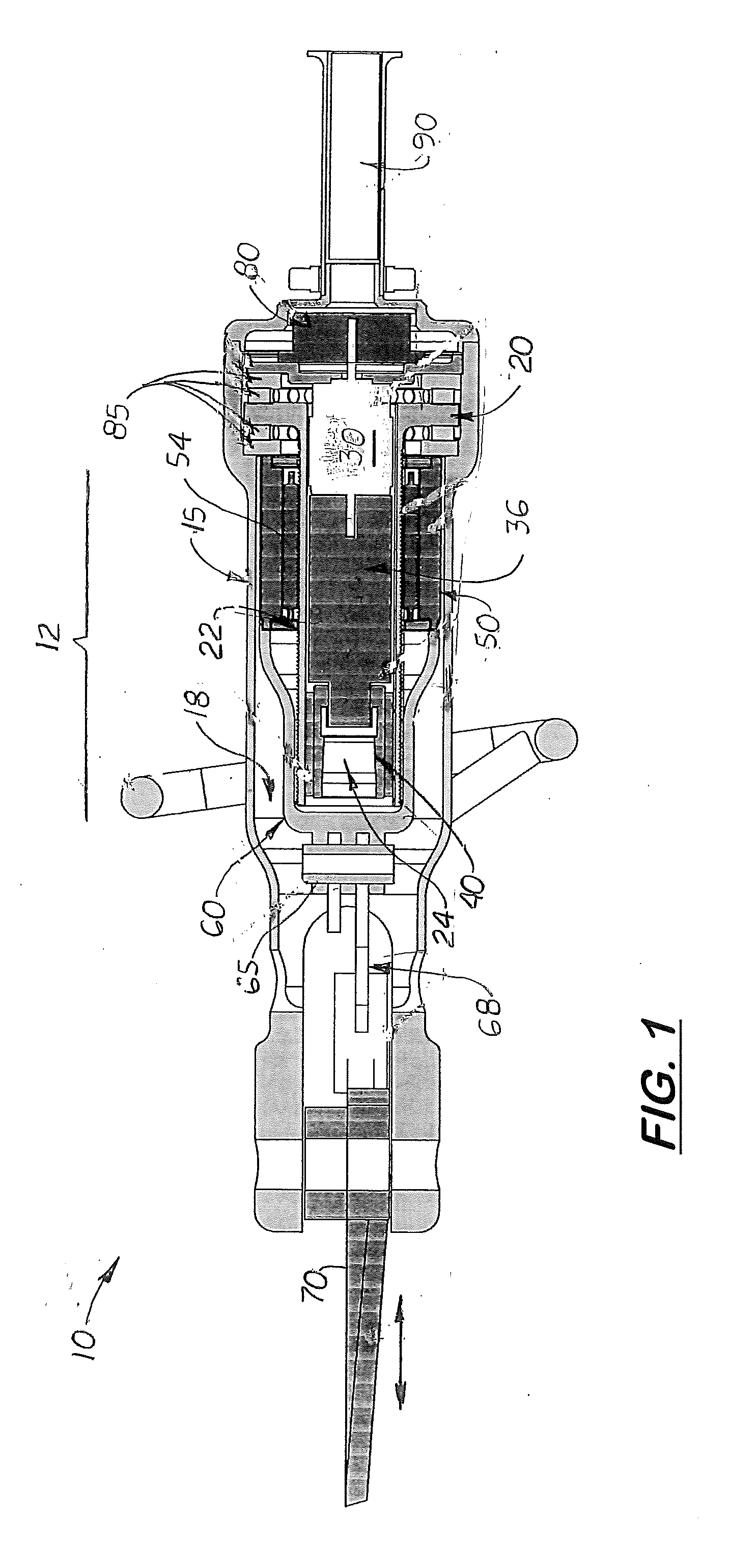
[0023]A tool 10 with a lightweight linear drive mechanism 12 in the tool's elongated body 15 and designed to provide 70,000 to 120,000 lbs of force to the tool's working implement 70. FIG. 1 discloses the tool 10 that includes a roller screw assembly shown and described in U.S. Pat. No. 7,044,017 and incorporated herein. The roller screw assembly roller screw shaft 20 and a nut body 50 mounted over the outer surface of the roller screw shaft 20. Disposed inside the nut body is a plurality of longitudinally aligned rollers 54 designed to remain in constant contact with formed grooves on the outer surface of the roller screw shaft 22 and grooves formed on the interior surface of the nut body 50 during operation. The rollers 54, however, can shift axially and be re-positioned with respect to both the nut body 50 and the roller screw shaft 22 as the roller screw shaft 22 is rotated while remaining in rolling contact with the nut body 50.

[0024]The grooves on the nut body 50 are helical o...

second embodiment

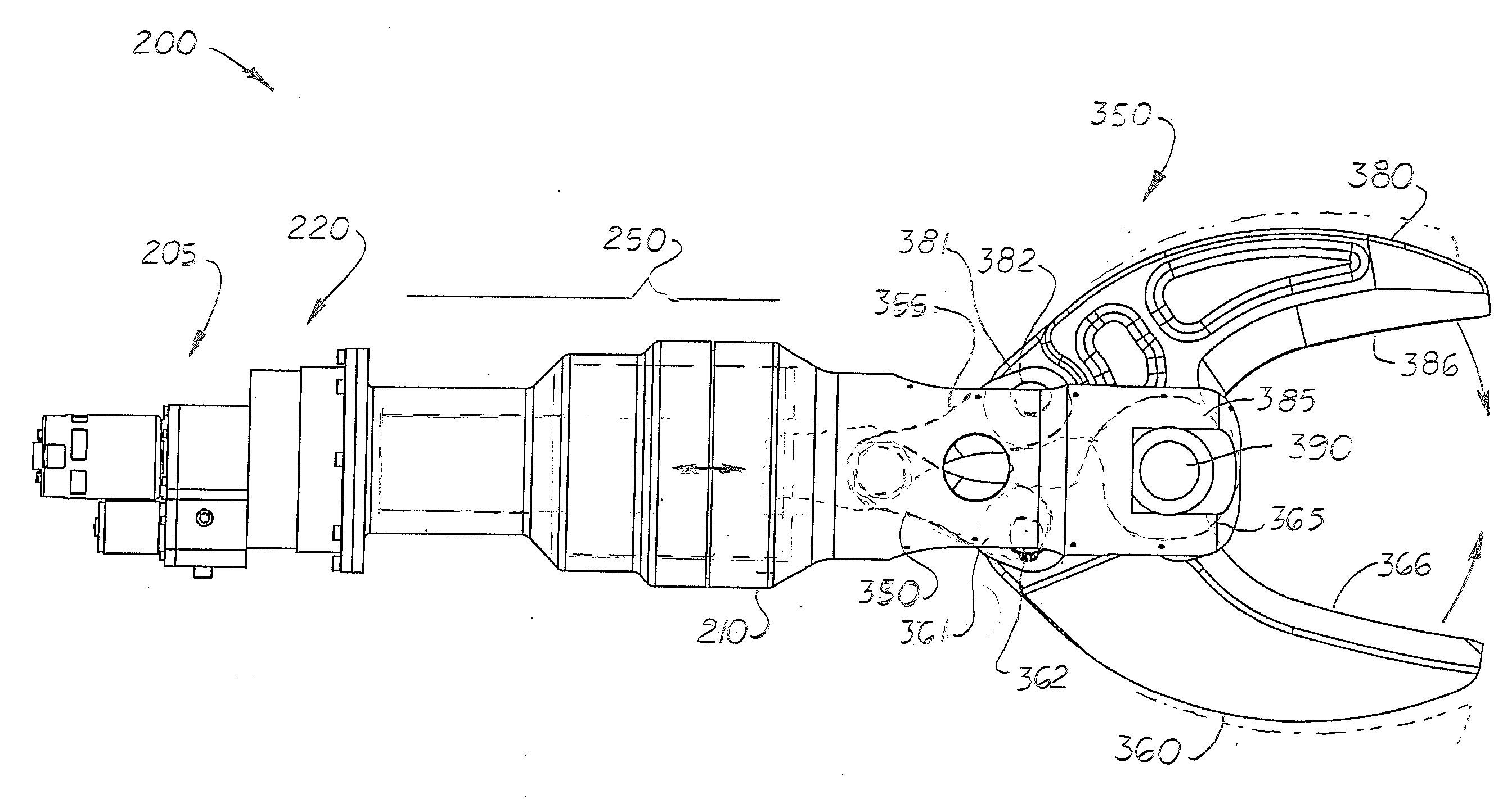
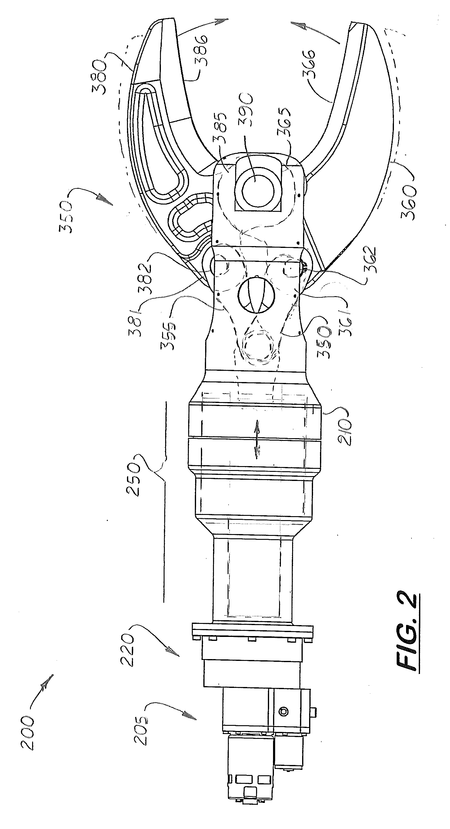
[0033]FIGS. 2-10 show the tool 200 with lightweight linear drive mechanism that uses an electric motor assembly 205 coupled to a multiple stage gear box 220 used in place of the frictional clutch. Coupled to the gear box 220 is a geared planetary roller screw 250 that is in place of the roller screw assembly described above. The geared planetary roller screw 250 is similar to the roller screw shown in U.S. Pat. No. 2,683,379 (Strandgren) which is now incorporated herein.

[0034]The geared planetary roller screw 250 includes a fixed cylindrical, fixed outer race 260 axially aligned inside the tool's outer housing 210. The outer race 260 includes a plurality of internal, non-helical grooves 264. A dowel pin 268 is inserted in between the outer housing 210 and the outer race 260 to hold the outer race 260 inside the tool 200. A set screw 270 is used to retain the dowel pin 268 in the outer housing 210.

[0035]Located adjacent inside the outer race 260 is a plurality of outer grooved roller...


PUM

PropertyMeasurementUnit
output rotationaaaaaaaaaa
forceaaaaaaaaaa
torqueaaaaaaaaaa

Abstract

A hand tool with a mechanical linear drive mechanism coupled to a linear activated working implement. The drive mechanism includes a geared planetary roller screw that includes a torque tube connected to a roller screw's nut body. The planetary roller screw includes a fixed outer race, a rotating set of grooved rollers axially aligned inside the outer race, a cylindrical nut body located inside the set of grooved roller, a plurality of inner rollers axially aligned and inside the nut body, a threaded shaft axially aligned and inside the inner rollers, and a torque tube axially aligned inside the inner rollers. The torque tube is connected at one end to a gear box which is coupled to an electric motor. When the electric motor is activated, the torque tube is rotated which causes a threaded shaft in the tool to move axially. A working implement is coupled to the distal end of the threaded shaft.

Description

TECHNICAL FIELD[0001]The present invention relates to voltage detectors, and more particularly, to voltage detectors that include a flashlight. This invention relates to linear drive mechanisms, and more particularly to linear drive mechanism that are portable and compact.BACKGROUND ART[0002]Portable hand tools are commonly used by emergency personnel to bend, spread or cut metal pieces to free drivers and passengers from their vehicles after accidents. The working implements on these hand tools are actuated by a linear mechanism coupled to a hydraulic cylinder. The hydraulic cylinder is coupled to a gas or electricity powered hydraulic pump.[0003]One drawback with power hand tools that use hydraulic pumps is the hydraulic pump's periodic inspection and maintenance requirements. Another drawback is the tool's housing is elongated to accommodate the hydraulic pump, the linear mechanism and the working implement.[0004]What is needed is a portable hand tool with an electric, non-hydrau...

Claims


Application Information

Patent Timeline
Patent Type & Authority Applications(United States)
IPC IPC(8): B23D17/04B23D29/00B26B15/00F16H25/22
CPCB23D17/04F16H25/2252B26B15/00B23D29/00
Inventor LAWLOR, SHAWNCORNELIUS, CHARLES
Owner CREATIVE MOTION CONTROL
Why Eureka
Try Eureka