Electronic circuit unit

a technology of electronic circuits and circuit boards, applied in the direction of printed circuit board receptacles, electrical apparatus casings/cabinets/drawers, coupling device connections, etc., can solve the problems of large stress circuit board is likely to be moved in the casing, and the conductive pattern and soldered portions formed on the printed circuit board are damaged or likely to occur, etc., to achieve easy prevention of rattling and large bending stress

Active Publication Date: 2016-02-11
ALPINE ELECTRONICS INC
View PDF49 Cites 8 Cited by
  • Summary
  • Abstract
  • Description
  • Claims
  • Application Information

AI Technical Summary

Benefits of technology

[0023]According to this aspect of the present disclosure, parts of the circuit board further to the inside than edge portions of the circuit board are supported by the support pieces formed by bending the first chassis. Thus, when an external force is applied to the connector, large bending stress can be prevented from acting on the circuit board, and accordingly, damage or the like to a conductive pattern and soldered portions is unlikely to be caused. Furthermore, the circuit board is positioned and held in the housing. Thus, when the electronic circuit unit is used as an on-vehicle device, the circuit board can be easily prevented from rattling.

Problems solved by technology

Thus, by repeatedly fitting and removing the plug into and from the connector, a problem in that a conductive pattern and soldered portions formed on the printed circuit board are damaged or is likely to occur.
Thus, when a large force is repeatedly applied to the connector, large stress is likely to act on the printed circuit board.
Furthermore, since the mass of a connector secured to the circuit board is comparatively large, the circuit board is likely to be moved in the casing.
In the case of on-vehicle equipment, the circuit board is likely to rattle.
However, with this structure, the number of man-hours for screwing in assembly is increased.
Furthermore, a space for screwing is required.
Thus, it is difficult to reduce the size.
Thus, a stress that damages the circuit board is unlikely to occur when an external force acts on the connector.
In particular, by supporting the circuit board at both sides of the connector, it is unlikely that large bending stress or the like will act on the circuit board.
In particular, the external force applied to the connector is unlikely to affect the circuit board when a part where the connector is secured is supported by the pressing projection.

Method used


Image

  • Electronic circuit unit
  • Electronic circuit unit
  • Electronic circuit unit

Examples


Embodiment Construction

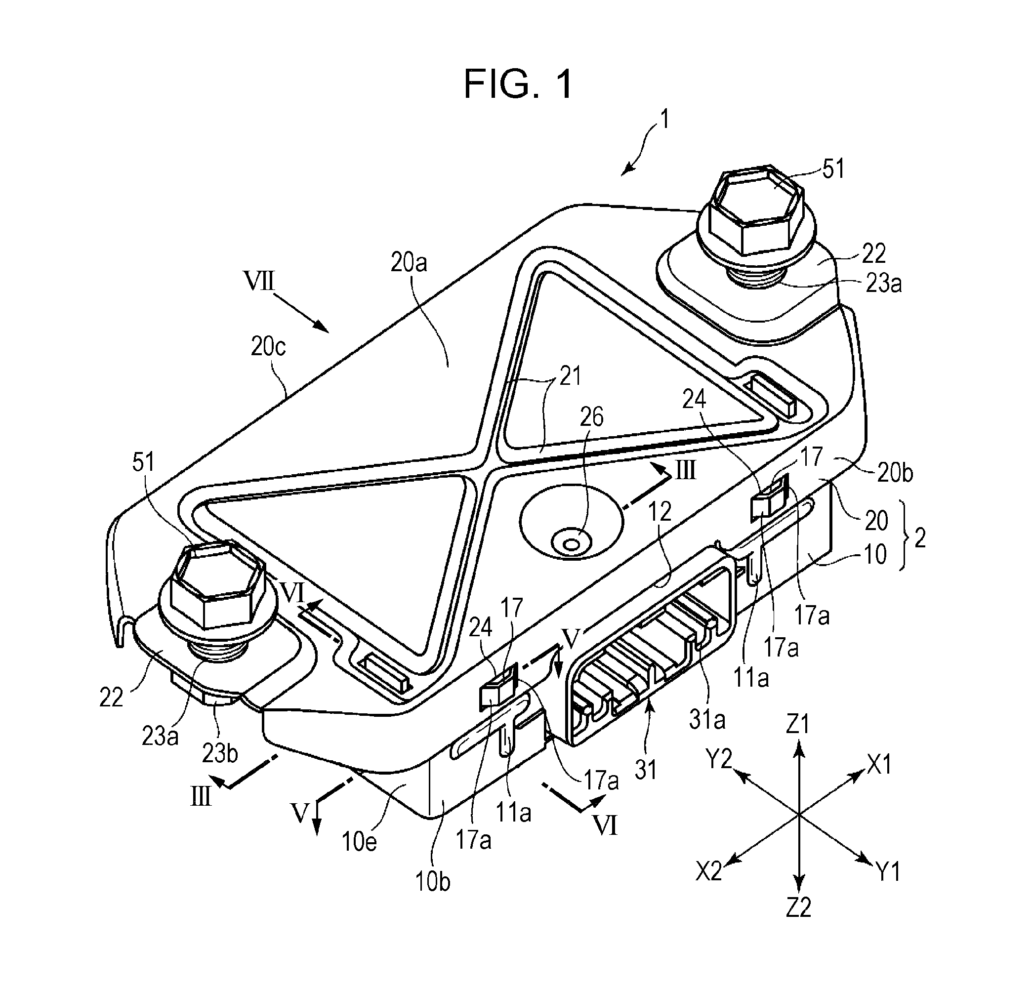
[0032]FIG. 1 illustrates an electronic circuit unit 1 used as an on-vehicle electronic device such as an active noise canceller.

[0033]In the electronic circuit unit 1, a Y1 direction is the forward direction, a Y2 direction is the rearward direction, an X1 direction is the rightward direction, an X2 direction is the leftward direction, a Z1 direction is the upward direction, and a Z2 direction is the downward direction.

[0034]A First Chassis and a Circuit Board

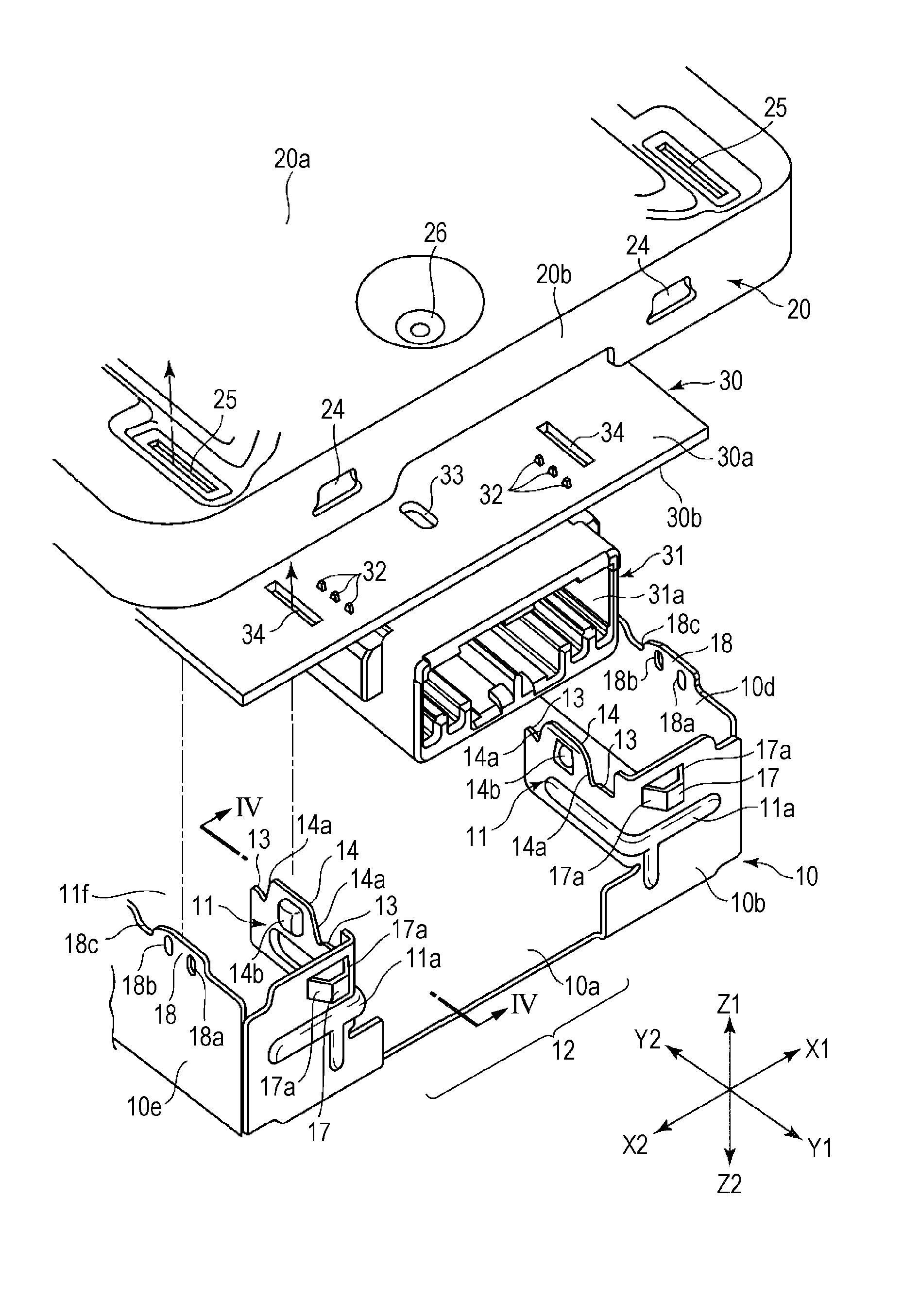
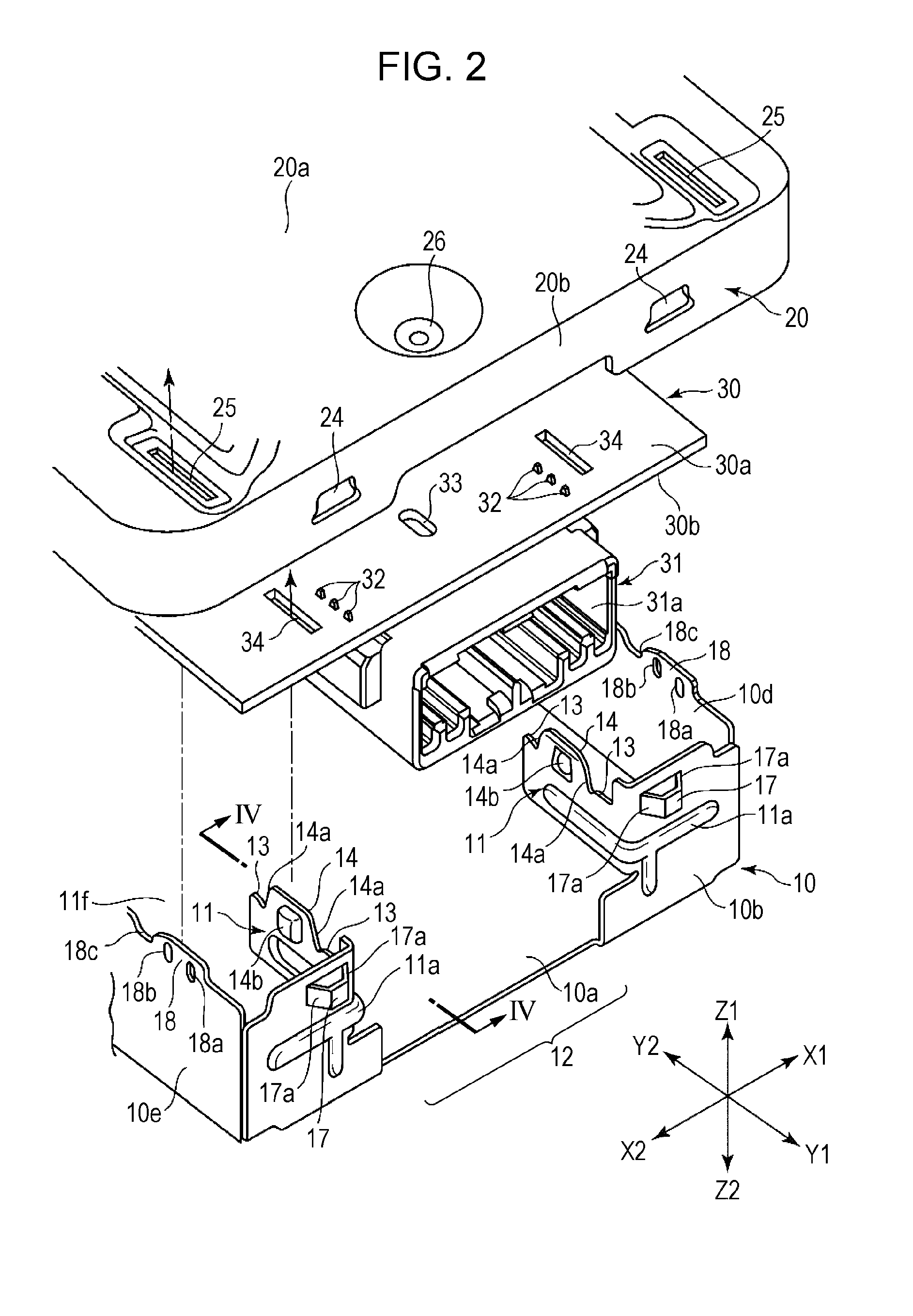
[0035]The electronic circuit unit 1 includes a housing 2. The housing 2 includes a first chassis 10 and a second chassis 20 that are combined with each other. The first chassis 10 and the second chassis 20 are formed by pressing a metal sheet such as a rolled steel sheet.

[0036]A circuit board 30 is housed in the housing 2. A connector 31 is secured to the circuit board 30. As illustrated in FIG. 2, the connector 31 is provided on a lower surface 30b of the circuit board 30 with terminals 32 of the connector 31 inserted into the...


PUM


Abstract

A housing includes a first chassis and a second chassis which are each formed of a metal sheet. Support projections integrally formed with support pieces formed in the first chassis are fitted into support holes of a circuit board on both left and right sides of a connector. A lower surface of the circuit board is supported by receiving portions formed in the support pieces, and part of the circuit board facing the connector is pressed downward by a pressing projection formed in the second chassis.

Description

RELATED APPLICATION[0001]The present application claims priority to Japanese Patent Application Number 2014-160332, filed Aug. 6, 2014, the entirety of which is hereby incorporated by reference.BACKGROUND[0002]1. Field of the Invention[0003]The present invention relates to an electronic circuit unit that includes a metal housing and a circuit board which is housed in the housing and to which a connector is secured.[0004]2. Description of the Related Art[0005]Japanese Unexamined Patent Application Publication No. 2002-314264 describes an invention relating to a casing that houses an electronic component. This casing includes a casing body that includes an upper casing body and a lower casing body which are formed of metal. A printed circuit board to which a connector is secured is housed in the casing body.[0006]An upwardly extending elastic engagement piece is formed in the lower casing body. The engagement piece is brought into engagement with a recess portion formed in the printed...

Claims


Application Information

Patent Timeline
Patent Type & Authority Applications(United States)
IPC IPC(8): H05K5/00H01R12/70H05K7/14
CPCH05K5/006H01R12/7076H05K7/1427H01R12/724H05K5/0052H05K5/0069
Inventor IGARI, YASUYUKIKIDA, SHINOBUWATANABE, TATSUYAOKABE, TAKAO
Owner ALPINE ELECTRONICS INC
Why Eureka
Try Eureka