Quick Connection Arrangements with Locking Mechanisms

Active Publication Date: 2016-02-18
BAKER HUGHES INC
View PDF5 Cites 8 Cited by
  • Summary
  • Abstract
  • Description
  • Claims
  • Application Information

AI Technical Summary

Benefits of technology

[0007]An alternate quick connection arrangement is described wherein the locking mechanism is a rotational locking mechanism. The securing sleeve is locked against rotation and axial movement with respect to the first and second tubular member by a ratchet-style anti-rotation lock. In a described embodiment, one or more radially-tapered anti-rotation tabs that are formed on the outer radial surface of the second tubular member. The securing sleeve has axially-extending collet fingers that have complementary anti-rotation tabs. Unthreading of the securing sleeve is prevented by the engagement between anti-rotation tabs on the secu

Problems solved by technology

In steerable drilling liner systems, the steer

Method used


Image

  • Quick Connection Arrangements with Locking Mechanisms
  • Quick Connection Arrangements with Locking Mechanisms
  • Quick Connection Arrangements with Locking Mechanisms

Examples


Embodiment Construction

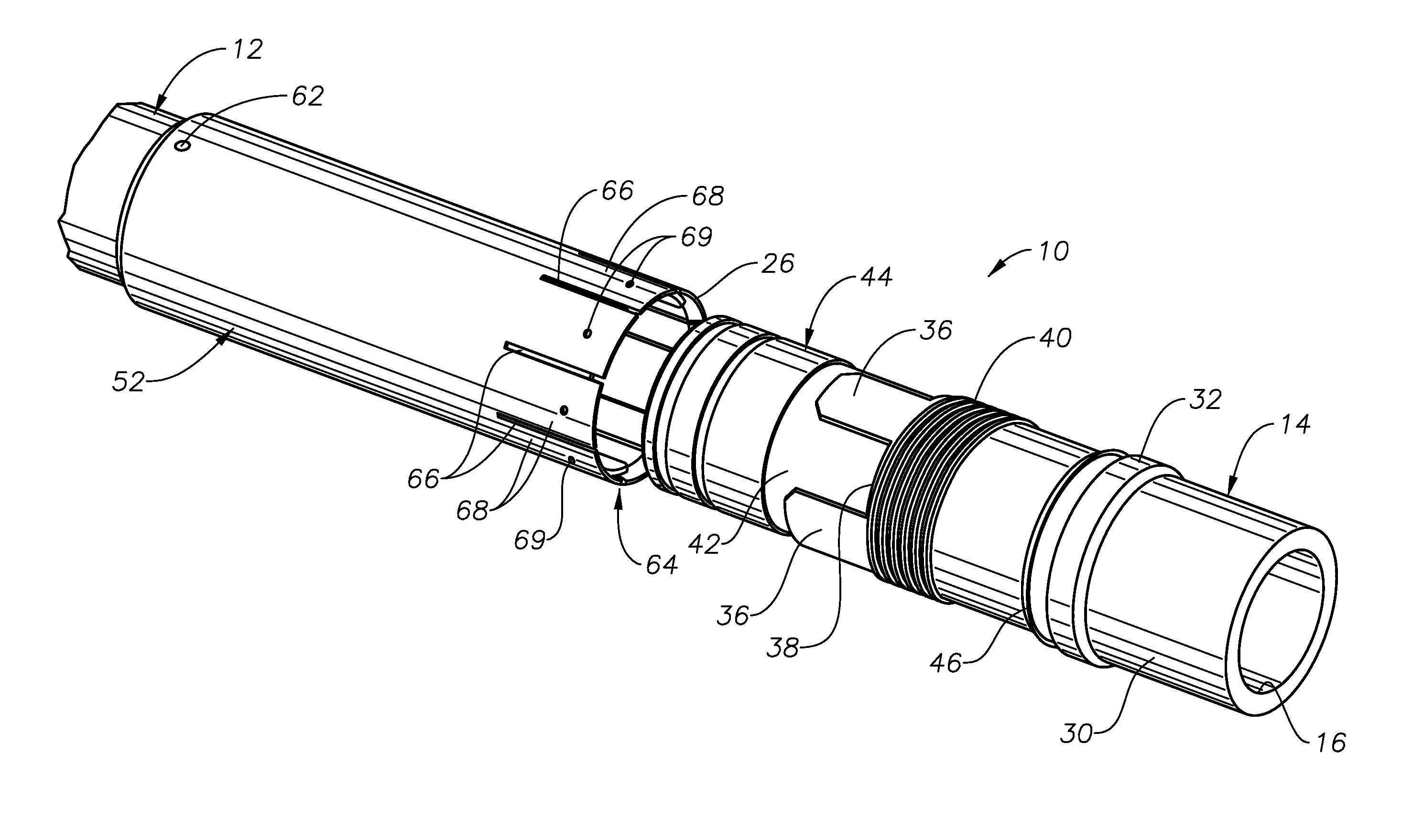
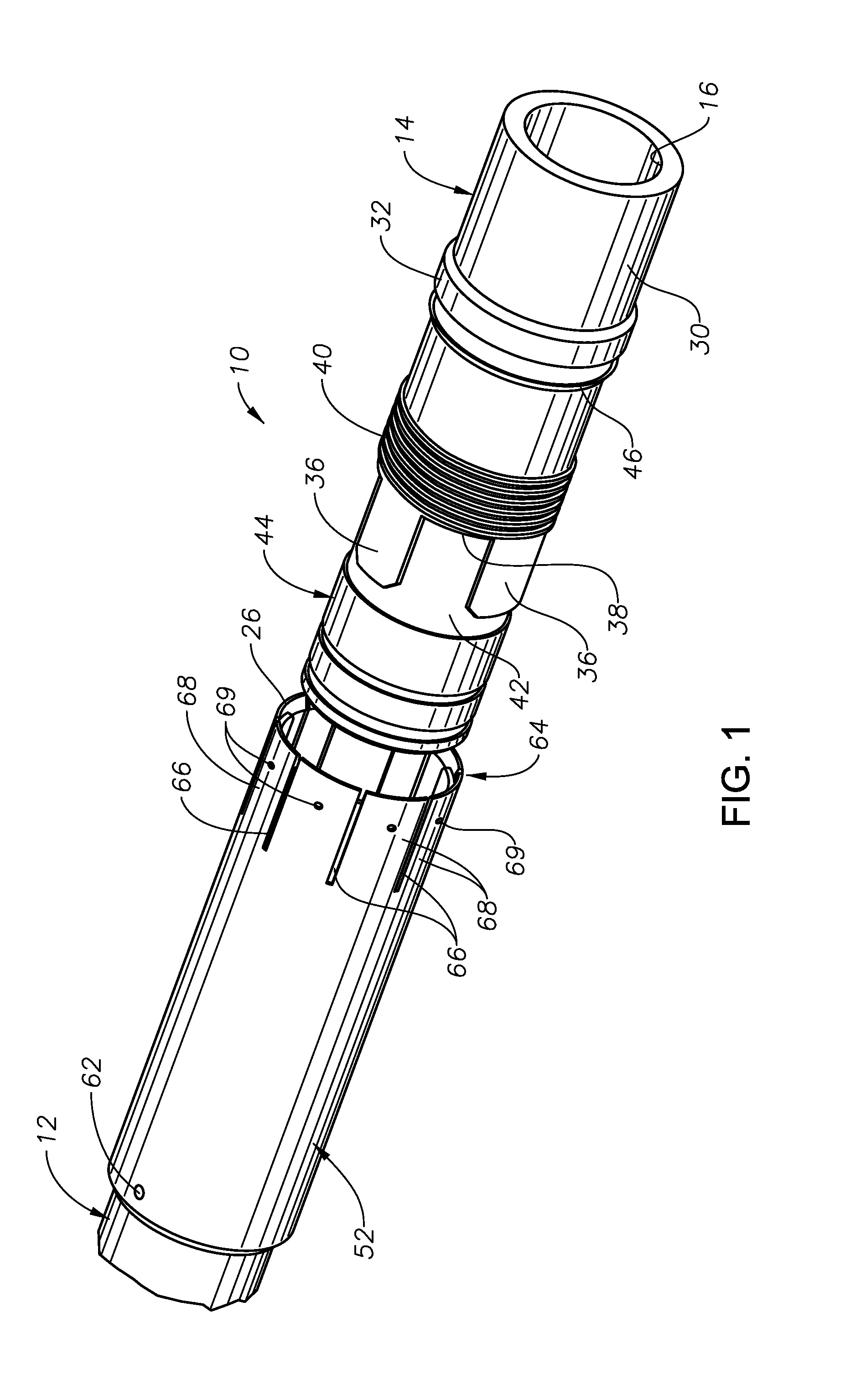
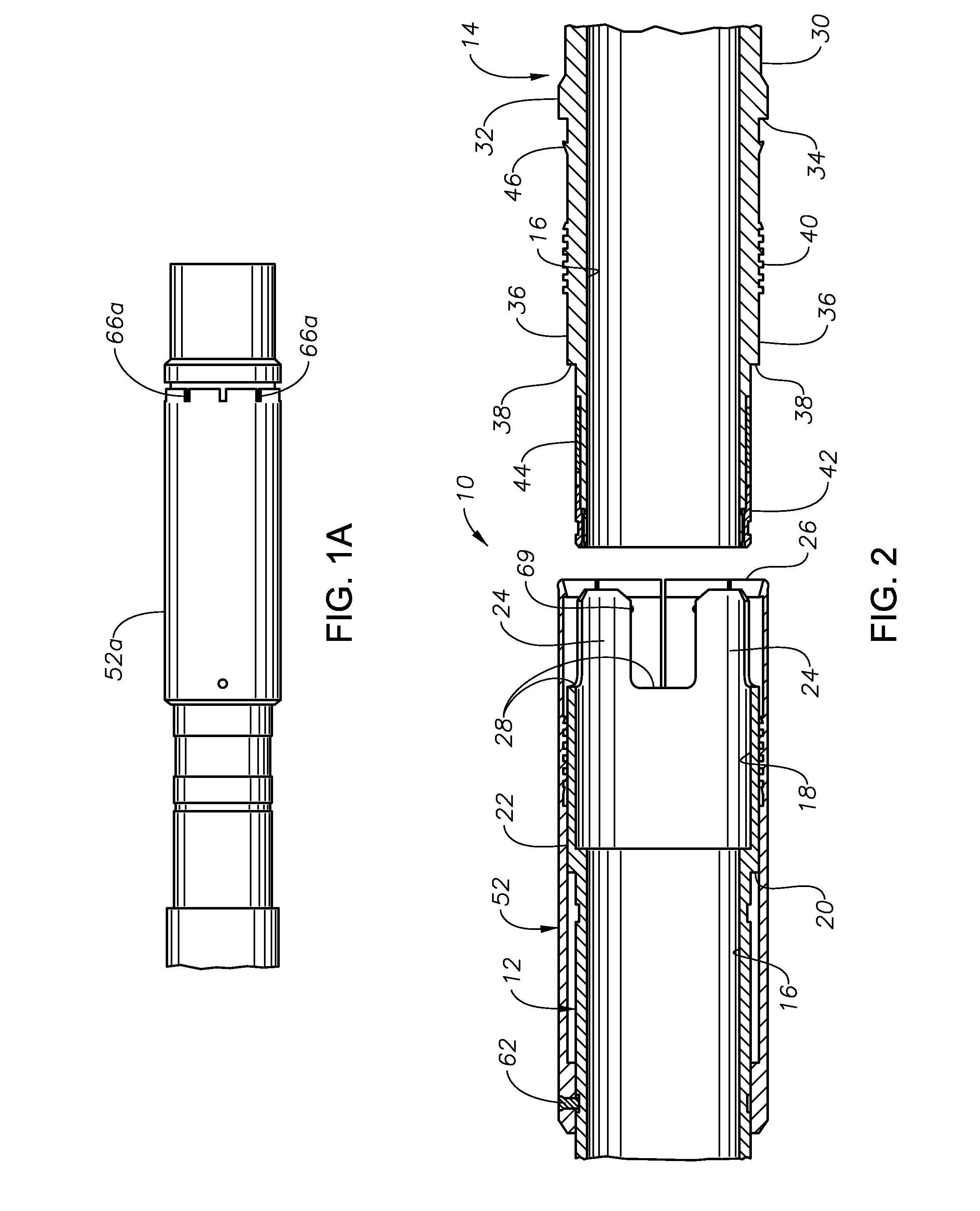
[0021]FIGS. 1-5 and 5A illustrate an exemplary quick connect arrangement 10 in which a first tubular member 12 and a second tubular member 14 are reversibly secured to each other in an end to end fashion. Each of the tubular members 12, 14 define a central axial bore 16 along its length.

[0022]The first tubular member 12 includes an enlarged diameter chamber portion 18. A stop shoulder 20 is formed on the outer radial diameter surface 22 of the first tubular member 12. Axially projecting fingers 24 are formed at the axial end 26 of the first tubular member 12. A recess 28 is formed between each pair of fingers 24.

[0023]The second tubular member 14 presents an outer radial surface 30 having a raised ring 32 which presents an axially-facing stop shoulder 34. Radially raised fingers 36 are formed upon the outer radial surface 30. Radially reduced recesses 38 are formed in between each pair of fingers 36. Preferably, the fingers 36 and recesses 38 are formed by machining the outer radial...


PUM

PropertyMeasurementUnit
Pressureaaaaaaaaaa
Angleaaaaaaaaaa

Abstract

Quick connect arrangements for securing together first and second tubular members. A securing sleeve helps secure the connection together and include locking arrangements which ensure that the securing sleeve cannot be inadvertently unthreaded.

Description

BACKGROUND OF THE INVENTION[0001]1. Field of the Invention[0002]The invention relates generally to devices and methods for rapidly interconnecting tubular members.[0003]2. Description of the Related Art[0004]In steerable drilling liner systems, the steerable liner is subject to high drag and torque. Tubular members should be connected prior to running in or during portions of the run-in operation in a manner that resists inadvertent uncoupling during operation.SUMMARY OF THE INVENTION[0005]The invention provides quick connect arrangements that allow two tubular members to be rapidly connected together and be secured against axial and rotational movement with respect to one another. According to particular aspects, the quick connect arrangements are designed to maintain internal pressure within the tubular members when interconnected. The devices and methods of the present invention are particularly useful for interconnecting sections of drilling liners used in steerable drilling ope...

Claims


Application Information

Patent Timeline
IPC IPC(8): F16L37/084F16L19/00F16L37/098
CPCF16L37/0847F16L19/00F16L37/098E21B17/08E21B7/20Y10T29/49881E21B17/043F16L15/08F16L21/08F16L37/113
Inventor VARGHESE, SIBUKRUEGER, MATTHEW
Owner BAKER HUGHES INC
Why Eureka
Try Eureka