
Antenna structure

Inactive Publication Date: 2016-02-18
RAINSUN
View PDF5 Cites 2 Cited by
  • Summary
  • Abstract
  • Description
  • Claims
  • Application Information

AI Technical Summary

Benefits of technology

The patent is about a new antenna structure that does not require an antenna to be printed on a circuit board or a flexible board, which reduces costs and prevents pollution. The antenna is encapsulated between two bonding films, which protect it from external damage and make it easier to manufacture. The new antenna is also easier to produce and reduces the time and cost of manufacturing.

Problems solved by technology

Thus, the manufacturing process of the conventional antenna structure tends to include an etching process, in which the process easily pollutes the environment and increases the cost of the conventional antenna structure.

Method used


Image

  • Antenna structure
  • Antenna structure
  • Antenna structure

Examples


first embodiment

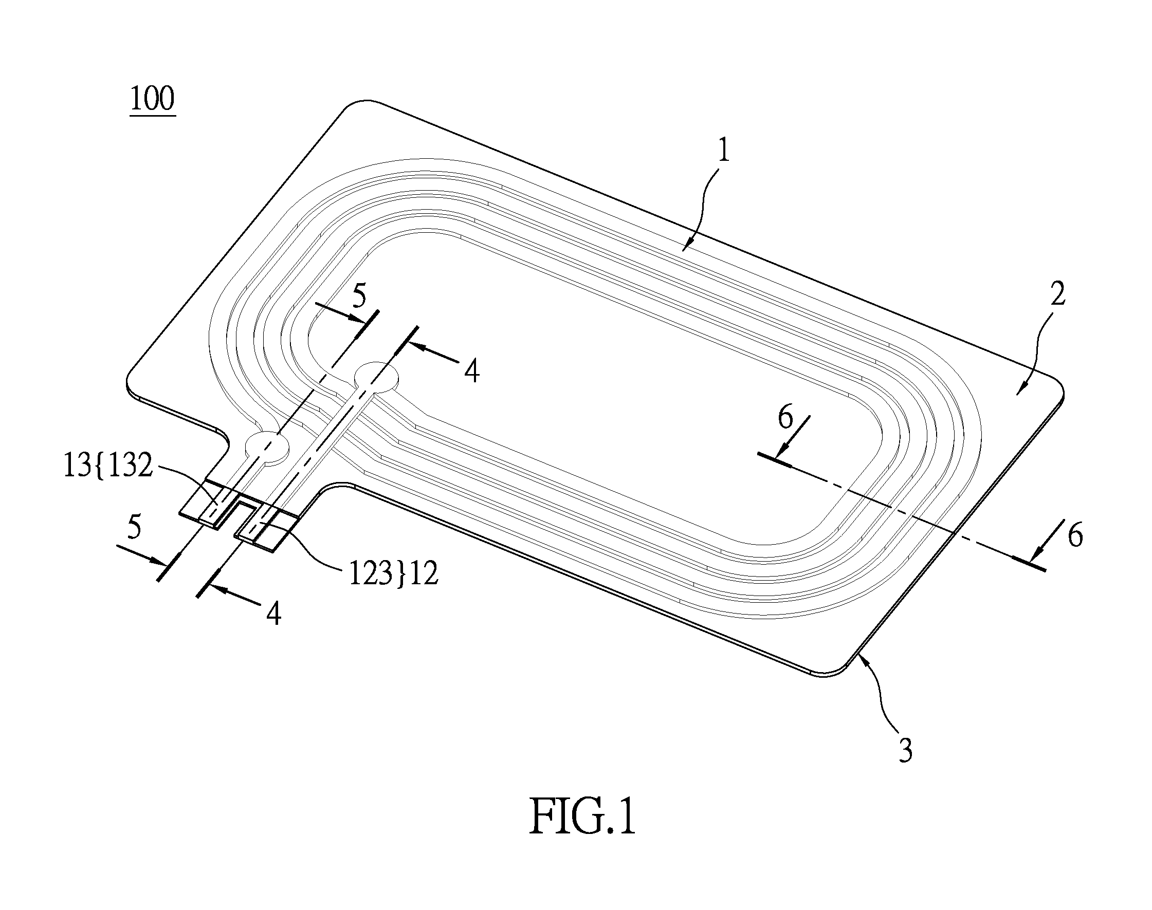
[0028]Please refer to FIGS. 1 through 10, which show an embodiment of the instant disclosure. References are hereunder made to the detailed descriptions and appended drawings in connection with the instant disclosure. However, the appended drawings are merely shown for exemplary purposes, rather than being used to restrict the scope of the instant disclosure.

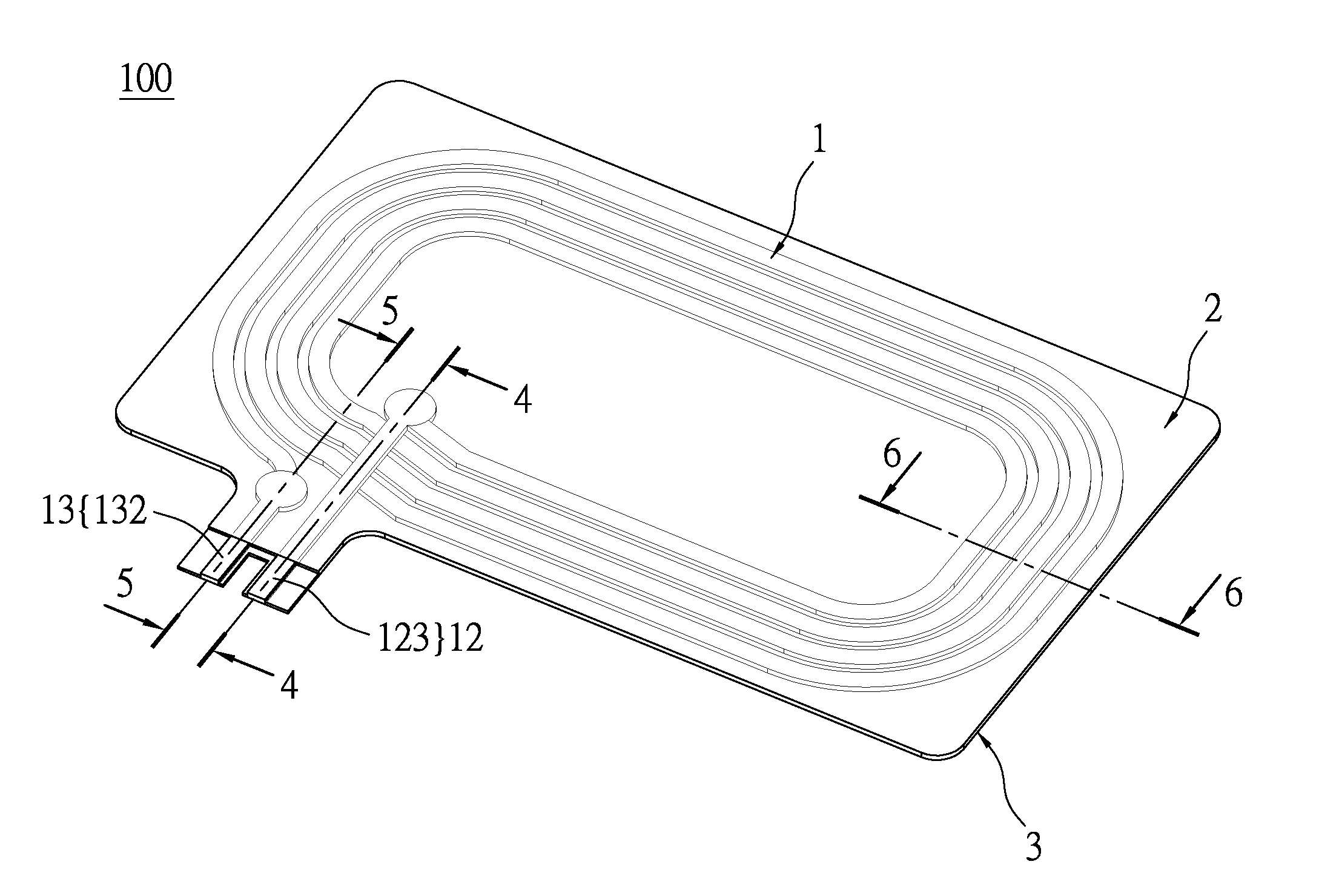
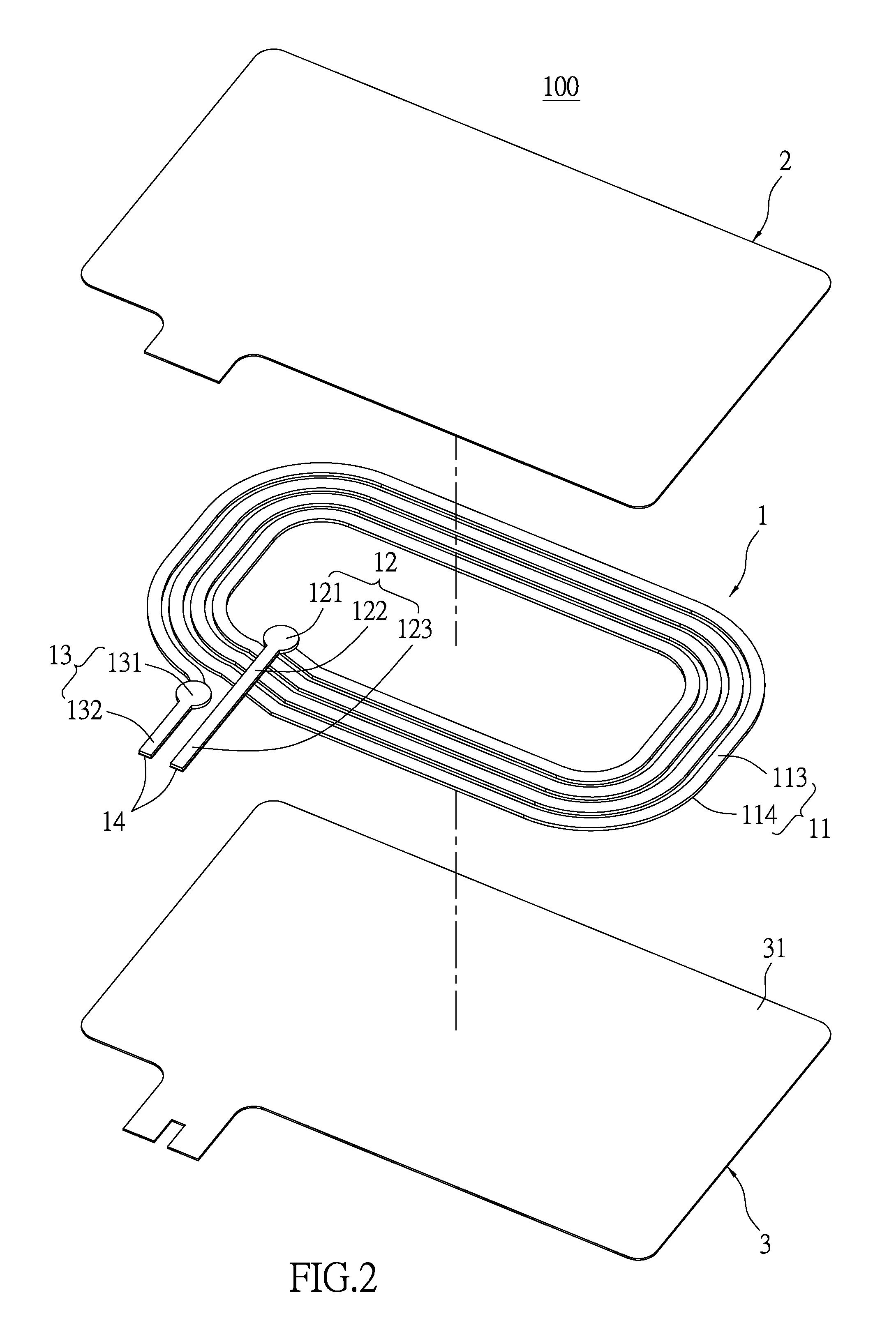
[0029]Please refer to FIG. 1, the instant embodiment discloses an antenna structure 100 for near field communication (NFC), but is not limited thereto. The antenna structure 100 has a bendable antenna 1, a bendable first bonding film 2, and a bendable second bonding film 3. The antenna 1 is approximately encapsulated between the first bonding film 2 and the second bonding film 3. The following description discloses each construction of the antenna 1, the first bonding film 2, and the second bonding film 3, and then further explains the relationship between the above components.

[0030]Please refer FIGS. 2 and 3, and occasionally r...

second embodiment

[0054]Please refer to FIGS. 11 through 15, which show a second embodiment of the instant disclosure. The second embodiment is similar to the first embodiment, so that the same features are not disclosed again. The difference between the first and second embodiments is that the main segment 11, the first connecting segment 12, and the second connecting segment 13 of the second embodiment are integrally formed in one piece. That is to say, the bonding portion 121 of the first connecting segment 12 is integrally extended from the inner end 111 of the main segment 11, and the bonding portion 131 of the second connecting segment 13 is integrally extended from the outer end 112 of the main segment 11.

[0055]In order to easily understanding the antenna structure 100 of the instant embodiment, the following description discloses the manufacturing method of the antenna structure 100. Please refer to FIGS. 11 through 14, which show the steps of the manufacturing method of the antenna structure...


PUM


Abstract

An antenna structure includes an antenna, a first bonding film, and a second bonding film. The antenna is bendable and has a main segment, a first connecting segment connected to the main segment, and a second connecting segment connected to the main segment. The antenna has a first surface and an opposite second surface, and the first and the second connecting segments are respectively configured to connect a ground and a signal source. Each one of the first bonding film and the second bonding film has an adhesive surface and is bendable. The first and second surfaces of the main segment are respectively adhered on the adhesive surfaces of the first and second bonding films. The adhesive surface of the first bonding film is adhered on the adhesive surface of the second bonding film, and the main segment is encapsulated between the first and second bonding films.

Description

BACKGROUND OF THE INVENTION[0001]1. Field of the Invention[0002]The instant disclosure relates to an antenna structure; more particularly, to an antenna structure without any printed circuit board (PCB) or any flexible printed circuit (FPC) board.[0003]2. Description of Related Art[0004]An antenna of the conventional antenna structure is formed on a printed circuit board or a flexible printed circuit board. Thus, the manufacturing process of the conventional antenna structure tends to include an etching process, in which the process easily pollutes the environment and increases the cost of the conventional antenna structure.[0005]To achieve the abovementioned improvement, the inventors strive via industrial experience and academic research to present the instant disclosure, which can provide additional improvement as mentioned above.SUMMARY OF THE INVENTION[0006]One embodiment of the instant disclosure provides an antenna structure without an antenna on any printed circuit board or ...

Claims


Application Information

Patent Timeline
IPC IPC(8): H01Q7/00
CPCH01Q7/00H01Q1/40
Inventor CHAN, YUAN-HANLEE, CHENG-LEI
Owner RAINSUN
Learn More