Vehicle control system and vehicle control method

a technology of vehicle control and control system, which is applied in the direction of gearing, transportation and packaging, hoisting equipment, etc., can solve the problems of taking time to achieve a target speed ratio and inability to smoothly perform speed change operation, so as to achieve smooth torque change of output shaft, reduce inertia torque, and achieve smooth torque change

Active Publication Date: 2016-02-25
TOYOTA JIDOSHA KK
View PDF1 Cites 12 Cited by
  • Summary
  • Abstract
  • Description
  • Claims
  • Application Information

AI Technical Summary

Benefits of technology

[0021]Thus, according to the present invention, the shifting operation of the geared transmission is started before the completion of engagement of the clutch to shift the transmission route from the route including the geared transmission to the route including the continuously variable transmission. Therefore, the speed change operation can be carried out smoothly while reducing an inertia torque. Specifically, torque of the output shaft can be changed smoothly to reduce a shift shock and discomfort during transmitting torque through the friction clutch with a predetermined transmitting capacity to switch the transmission route. The speed change operation can be further smoothened by equalizing a change rate of a speed ratio of the continuously variable transmission with a change rate of a speed ratio between a rotational speed of the input shaft and a rotational speed of the output shaft (i.e., a total speed ratio). Specifically, during switching the transmission route, the engagement of the clutch is started first, and then the shifting operation of the geared transmission is started. Therefore, the total speed ratio can be changed promptly to the target ratio without delay so that speed change response can be improved. In addition, since the shift shock can be reduced without increasing a required time for the clutch-to-clutch shifting, damage of a friction material of the friction clutch can be reduced to elongate lifetime thereof.

Problems solved by technology

For this reason, a speed change operation may not be performed smoothly.
In addition, it may take time to achieve a target speed ratio calculated based on a vehicle speed.

Method used


Image

  • Vehicle control system and vehicle control method
  • Vehicle control system and vehicle control method

Examples


Embodiment Construction

)

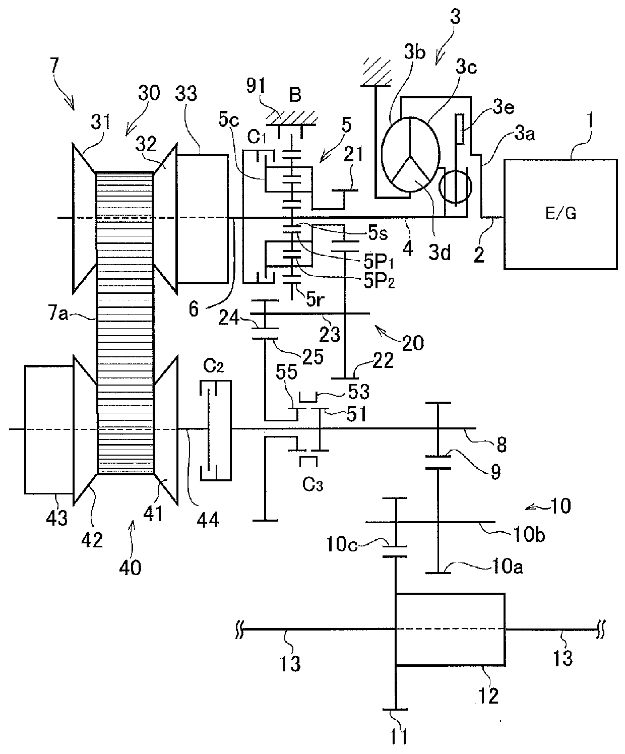
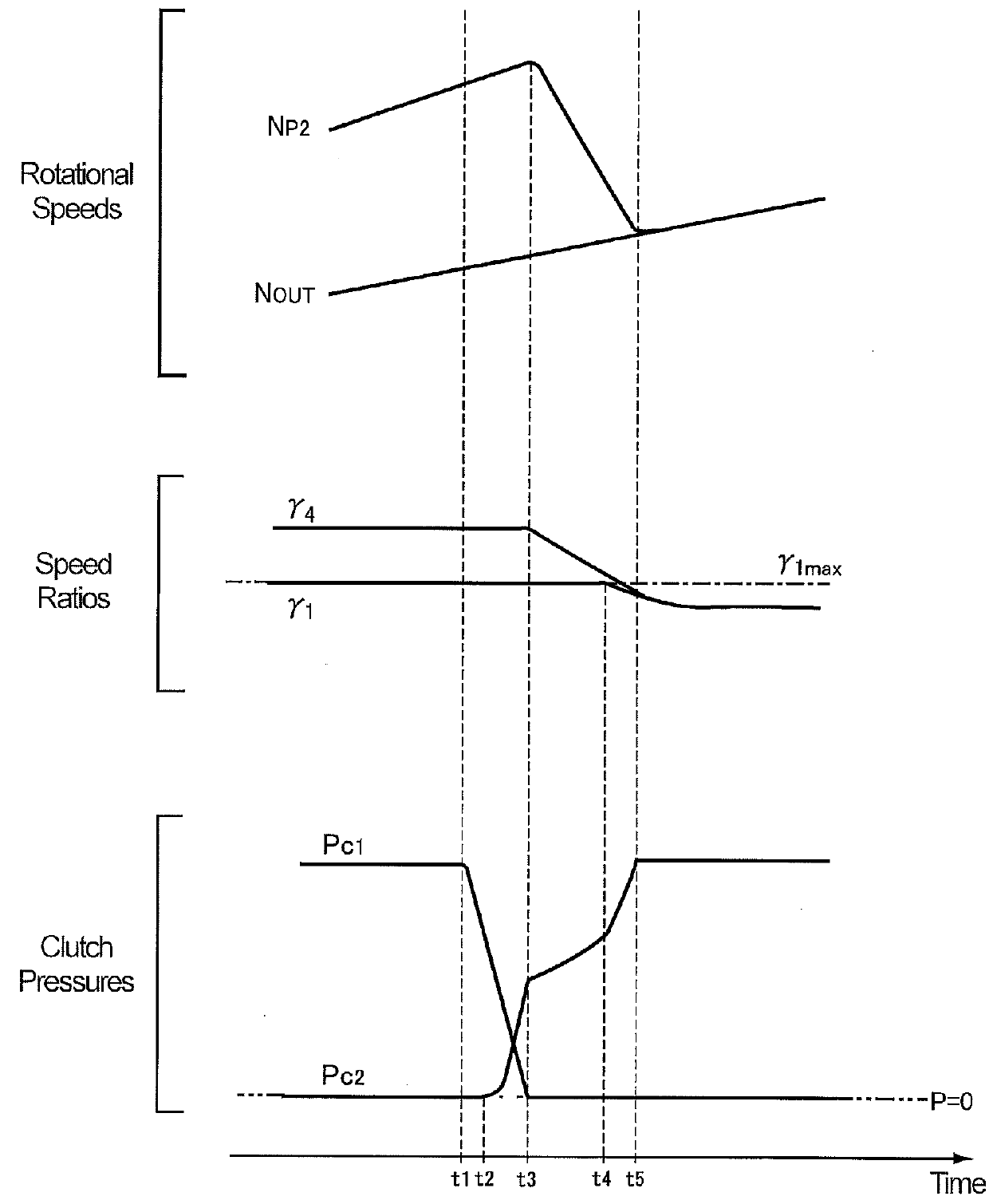
[0025]Preferred example of the present invention will be explained hereinafter. The vehicle control system according to the present invention is applied to a vehicle comprising a continuously variable transmission adapted to change a speed ratio continuously and a geared transmission adapted to select a gear stage from a plurality of fixed stages. In the vehicle, the continuously variable transmission and the geared transmission are arranged parallel to each other between an input shaft to which a power of a prime move is delivered and an output shaft. The vehicle further comprises a clutch device adapted to switch a power transmission route from a route including the continuously variable transmission and a route including the geared transmission. The present invention is configured to actuate the clutch device while activating the continuously variable transmission when switching the power transmission route from the route including the geared transmission to the route including ...


PUM


Abstract

Vehicle control system and method provided to change speed ratio smoothly when switching a power transmission route from a route including a geared transmission to a route including a continuously variable transmission. Vehicle control system applied to a vehicle comprising: continuously variable transmission for changing speed ratio continuously is disposed between input shaft and output shaft; geared transmission is disposed parallel to the continuously variable transmission, and is adapted to establish speed ratio that cannot be established by continuously variable transmission; and friction clutch is brought into engagement to switch torque transmission route from a route including the geared transmission to a route including the continuously variable transmission. Vehicle control system configured to start speed change operation of continuously variable transmission before the friction clutch is brought into engagement completely when switching torque transmission route from the route including the geared transmission to the route including the continuously variable transmission.

Description

TECHNICAL FIELD[0001]The present invention relates to a control system and a control method for a vehicle in which a geared transmission adapted to establish fixed gear stages and a continuously variable transmission adapted to change a speed ratio continuously are arranged parallel to each other between an input shaft and an output shaft.BACKGROUND ART[0002]Vehicles in which a geared transmission and a continuously transmission are arranged parallel to each other between an input shaft to which a power of the prime mover is delivered and an output shaft are known in the conventional art. The geared transmission is adapted to select a fixed gear stage from a plurality of gear stages, and the continuously variable transmission is adapted to change a speed ratio continuously. In the vehicle of this kind, a clutch is arranged to switch a power transmission route between a route including the geared transmission and a route including the continuously variable transmission. It is also kn...

Claims


Application Information

Patent Timeline
Patent Type & Authority Applications(United States)
IPC IPC(8): B60W30/19B60K17/00B60W10/02B60W10/107F16H37/02F16H59/14F16H59/46F16H59/48F16H59/68F16H61/02F16H61/04F16H61/662
CPCB60W30/19B60W2710/1005F16H61/662F16H59/48F16H59/14F16H59/68F16H59/46F16H61/04B60W10/02B60W10/107F16H61/0262B60K17/00F16H2059/6807F16H2059/683B60W2510/1045B60W2710/021F16H37/021F16H61/66259F16H2037/026F16H37/022B60W10/115B60W2510/0275
Inventor MATSUO, KENJIOHGATA, YUSUKEINOUE, DAISUKEAYABE, ATSUSHIKIMURA, MOTONORIISHIKAWA, SHUHEIHINO, AKIRAKONDO, HIROKI
Owner TOYOTA JIDOSHA KK
Why Eureka
Try Eureka