Electric detonator and method for producing an electric detonator

a technology of electric detonators and electric detonators, which is applied in the direction of ammunition fuzes, nitrated metallo-organic explosive compositions, explosives, etc., can solve the problems of azide as the primary explosive show and impaired functioning at low temperatures, and achieve flexible and simple production processes, compact design

Active Publication Date: 2016-02-25
SAAB AB
View PDF50 Cites 4 Cited by
  • Summary
  • Abstract
  • Description
  • Claims
  • Application Information

AI Technical Summary

Benefits of technology

[0020]The invention signifies a number of advantages and effects, the most important being: the electric detonator is environmentally friendly, withstands a wide range of temperatures and allows a compact design. Layered application of the primary explosives and the secondary explosive in the cap allows a flexible and simple production process.
[0021]The invention has been defined in the following patent claims and will now be described in somewhat greater detail in connection with the appended FIGURE.

Problems solved by technology

However, trials conducted with just silver azide as the primary explosive show impaired functioning at low temperatures.

Method used


Image

  • Electric detonator and method for producing an electric detonator

Examples


Embodiment Construction

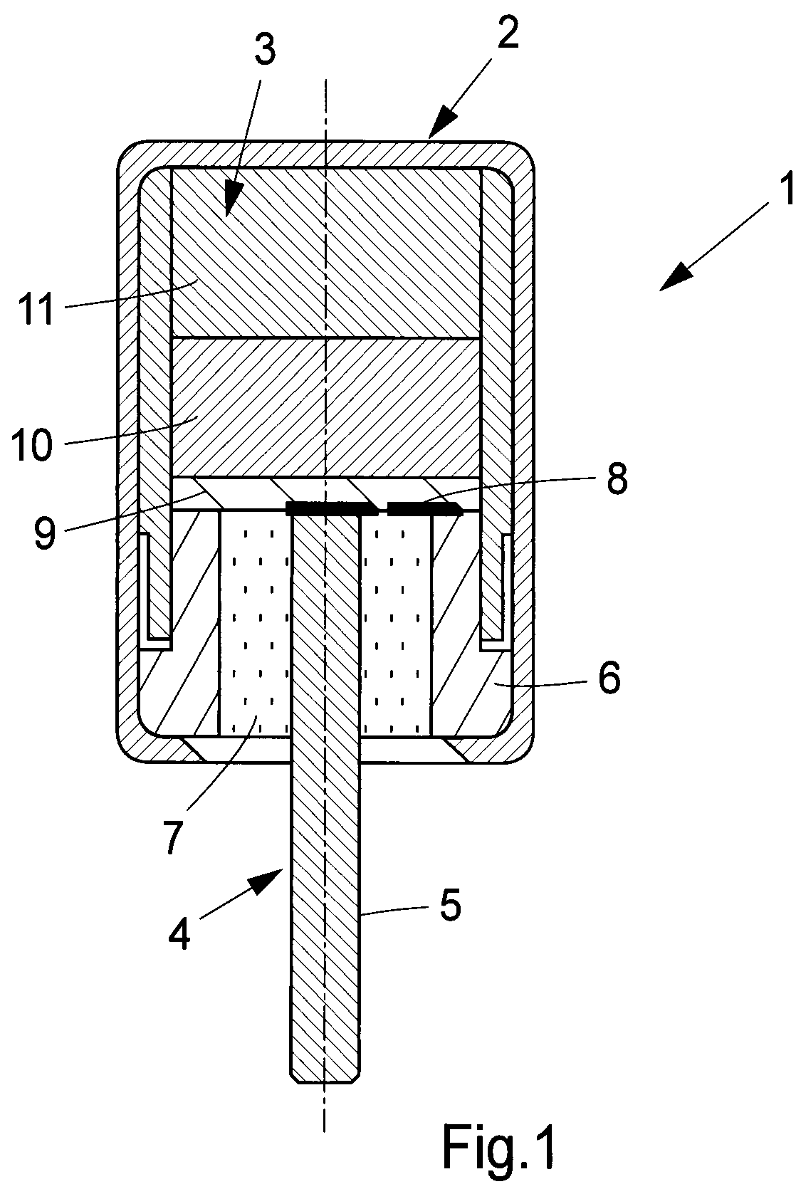
[0024]The electric detonator 1 in FIG. 1 comprises a cap 2, which comprises a priming charge 3 and an electrode 4 for initiation of the said priming charge 3, wherein the said electrode 4 comprises a positive pole, configured as a rod or pin 5 axially arranged in the cap 2, and a negative pole, configured as a socket 6 coaxially arranged with the pin 5, the said cap 2 also comprising a resistor element 8 arranged between the pin 5 of the positive pole and the socket 6 of the negative pole. In an alternative embodiment (not shown), the negative pole is instead constituted by the pin 5 and the positive pole by the socket 6. The positive pole and the negative pole are electrically insulated from each other via an electrical insulator 7, comprising glass, a plastic or a ceramic material, such as, for example, porcelain or steatite, also referred to as soapstone.

[0025]The electric detonator 1 further comprises a resistor element 8 disposed, in bridging arrangement, between the centrally ...


PUM


Abstract

The present invention relates to an electric detonator (1) comprising a cap (2), comprising a priming charge (3) and an electrode (4), comprising a positive pole, a negative pole and a resistor element (8), the said priming charge (3) comprising at least two primary explosives, a first primary explosive (9) and a second primary explosive (10), and at least one secondary explosive (11). The electric detonator is characterized in that the two primary explosives (9, 10) and the secondary explosive (11) are arranged in layers, in an increasing degree of sensitivity, bearing one against the other, wherein the first primary explosive (9), constituting the most sensitive of the two primary explosives (9, 10), is arranged closest to the resistor element (8), and in that the second primary explosive (10) is arranged thereafter between the first primary explosive (10) and the secondary explosive (11). The invention also relates to a production method for the said electric detonator (1).

Description

TECHNICAL FIELD[0001]The present invention relates to a lead-free electric detonator.BACKGROUND AND PRIOR ART[0002]Conventional electric detonators, also referred to as electric detonating caps, normally comprise primers, also referred to as primary explosives, which contain lead, for example lead azide (Pb(N3)2) or silver azide (AgN3) and lead trinitroresorcinol (2,4,6-trinitrobenzene-1,3-diol). Lead trinitroresorcinol is used to increase sensitivity, especially at low temperatures.[0003]New and intensified environmental requirements mean that lead-containing primers must be replaced with environmentally friendly alternatives. However, trials conducted with just silver azide as the primary explosive show impaired functioning at low temperatures.[0004]There is therefore a need for lead-free electric detonators having improved low temperature characteristics. There is also a need for lead-free electric detonators which are smaller and lighter than present-day lead-free electric deton...

Claims


Application Information

Patent Timeline
Patent Type & Authority Applications(United States)
IPC IPC(8): F42C19/12F42B33/00
CPCF42B33/001F42C19/12F42B3/103F42B3/124F42B3/128C06B25/34C06B35/00C06B41/06F42B3/12
Inventor EDSTROM, KARLOSTLUND, JOHAN
Owner SAAB AB
Why Eureka
Try Eureka