Flow meter and related system and apparatus

Active Publication Date: 2016-02-25
DEKA PROD LLP
View PDF1 Cites 127 Cited by
  • Summary
  • Abstract
  • Description
  • Claims
  • Application Information

AI Technical Summary

Benefits of technology

[0190]In certain embodiments of the present disclosure, an intravenous administration set includes: a flexible tube for directing fluid flow therewithin; a first port at a first end of the flexible tube; a second port at a second end of the flexible tube; a curved, elongated support member elastically deformable and having firs

Problems solved by technology

Typically, such applications use an infusion pump, but such pumps may not be used in all situations or environments.
Changes in

Method used


Image

  • Flow meter and related system and apparatus
  • Flow meter and related system and apparatus
  • Flow meter and related system and apparatus

Examples


Embodiment Construction

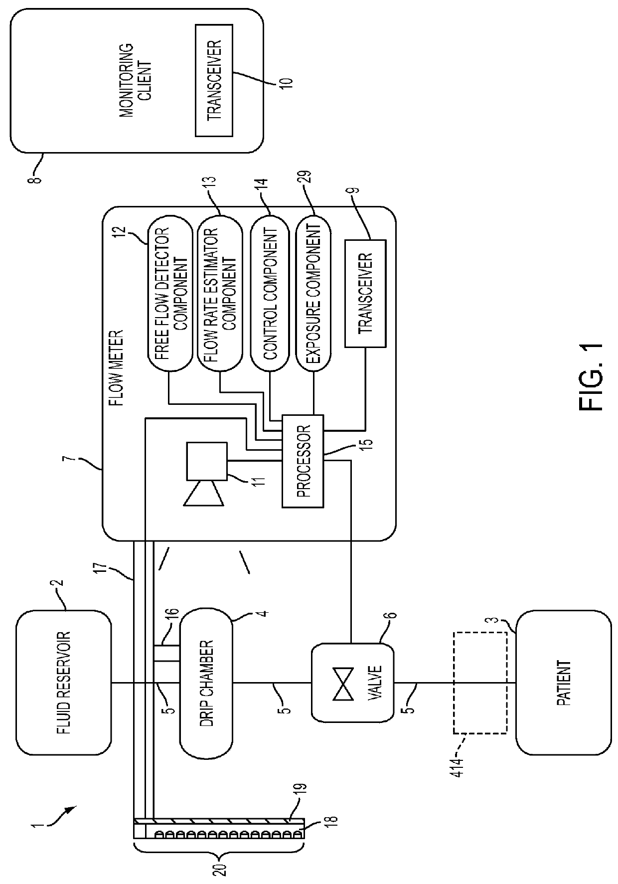
[0459]FIG. 1 shows a block diagram of a system 1 for regulating fluid flow in accordance with an embodiment of the present disclosure. For example, system 1 may regulate, monitor, and / or control the flow of fluid into a patient 3. The system 1 includes a fluid reservoir 2 for infusing fluid contained therein into the patient 3. The fluid reservoir 2 is gravity fed into a drip chamber 4 via a fluid tube 5. The fluid reservoir 2, the drip chamber 4, and the patient 3 may be considered as part of the system 1 or may be considered as separate or optional work pieces for the system 1 (e.g., any fluid reservoir 2 and drip chamber 4 may be used to treat any patient 3).

[0460]A flow meter 7 monitors the drip chamber 4 to estimate a flow rate of liquid flowing through the drip chamber 4. The fluid from the drip chamber 4 is gravity fed into a valve 6. The valve 6 regulates (i.e., varies) the flow of fluid from the fluid reservoir 2 to the patient 3 by regulating fluid flow from the drip chamb...


PUM


Abstract

A flow meter includes an image sensor and a processor. The image sensor is configured to capture an image of a drip chamber. The processor is configured to determine whether the captured image of the drip chamber contains a match to a template, and to apply a blurring function to the image captured by the image sensor of the drip chamber such that the processor can determine if the captured image contains a match to the template.

Description

CROSS REFERENCE TO RELATED APPLICATIONS[0001]The present application is a continuation application of U.S. patent application Ser. No. 14 / 213,373, entitled Flow Meter and Related System and Apparatus, (Attorney Docket No. L83) filed on Mar. 14, 2014, now U.S. Publication No. US-2014-0318639-A1, published on Oct. 30, 2014, which is a Non-Provisional application which claims the benefit of U.S. Provisional Patent Application Ser. No. 61 / 900,431, filed Nov. 6, 2013 and entitled System, Method, and Apparatus for Monitoring, Regulating, or Controlling Fluid Flow (Attorney Docket No. K52), which is hereby incorporated herein by reference in its entirety.[0002]U.S. patent application Ser. No. 14 / 213,373, entitled Flow Meter and Related System and Apparatus, (Attorney Docket No. L83) filed on Mar. 14, 2014, now U.S. Publication No. US-2014-0318639-A1, published on Oct. 30, 2014 is also a Continuation-In-Part of U.S. patent application Ser. No. 13 / 834,030, filed Mar. 15, 2013, and entitled S...

Claims


Application Information

Patent Timeline
IPC IPC(8): G06T7/20A61M5/14A61M5/168A61M5/172G05B15/02G05D7/06G06T3/00G06V10/141G06V10/30G06V10/75H04N5/225H04N7/18
CPCG06T7/20G05D7/0635G05B15/02H04N7/18A61M5/172G06K9/6201G06T3/0093A61M5/16804A61M5/1411H04N5/2256A61M5/1689A61M5/16877A61M5/16886A61M2205/3306A61M2205/3334A61M2205/50A61M39/284G06V10/141G06V10/30G06V10/75G06V10/761G06F18/22F16K27/00G01F1/661G06T5/002G06T5/50G06T7/0012G06T7/60H04N7/183G06T2207/20182G06T2207/20224G06T2207/30004G06T2207/30232Y10T137/7287G16H20/17G16H40/67G16H40/40A61M5/14A61M5/14212A61M5/16881A61M39/281A61M2005/14208A61M2205/3576A61M2205/502B65D47/2018F16K1/00F16K7/04F16K7/06F16K31/02F16M11/041F16M13/00F16M13/022G01F11/30G06V30/19073G06V10/42G06V10/758
Inventor PERET, BOB D.KANE, DEREK G.KAMEN, DEANMURPHY, COLIN H.KERWIN, JOHN M.
Owner DEKA PROD LLP
Why Eureka
Try Eureka