Enabling virtual machines access to switches configured by different management entities

a technology of management entities and virtual machines, applied in data switching networks, multi-programming arrangements, instruments, etc., can solve problems such as network management overhead, tight coupling between physical compute infrastructure and compute management layers, and network management overhead

Active Publication Date:
View PDF6 Cites 102 Cited by
  • Summary
  • Abstract
  • Description
  • Claims
  • Application Information

AI Technical Summary

Benefits of technology

[0004]Methods and systems for virtual switch management are provided to assist the creation and consumption of workflows for logical networks (also referred to as virtual networks) and network services configured through any cloud management system (CMS) while remaining independent of the compute manager and virtualization software vendor and version. In some embodiments, the edge of the logical network infrastructure is controlled by a single networking platform that is decoupled from the compute manager and the CMS. In these embodiments, the logical network infrastructure is controlled by a higher level networking specific construct better equipped to present network centric viewpoint than the compute manager. The networking platform adds a layer of indirection that allows decoupling of datacenter infrastructure software.

Problems solved by technology

Today, the network presents a significant management overhead, especially in the virtual infrastructure.
This raises an issue that is front and center in the vision of software defined datacenter.
One of the drawbacks of the current networking architecture is its tight coupling to the physical compute infrastructure and compute management layers.

Method used


Image

  • Enabling virtual machines access to switches configured by different management entities
  • Enabling virtual machines access to switches configured by different management entities
  • Enabling virtual machines access to switches configured by different management entities

Examples


Embodiment Construction

[0027]In the following detailed description of the invention, numerous details, examples, and embodiments of the invention are set forth and described. However, it will be clear and apparent to one skilled in the art that the invention is not limited to the embodiments set forth and that the invention may be practiced without some of the specific details and examples discussed.

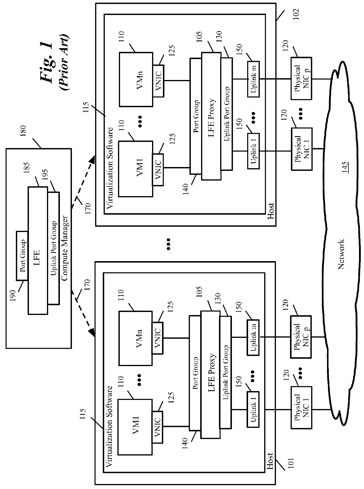
[0028]Virtualization is the ability to simulate a hardware platform, such as a server, storage device or network resource, in software. A virtual machine (VM) is a software implementation of a machine such as a computer. Logical networks are abstractions of a physical network. VMs may communicate using logical networks. FIG. 1 conceptually illustrates a legacy virtualized infrastructure domain that uses a legacy logical forwarding element (LFE) model that relies on compute manager as the source of truth for the LFE. The compute manager is a component of the cloud management system (CMS) that is used to create ...


PUM


Abstract

A method of configuring a plurality of logical forwarding elements (LFEs) on a physical computing device comprising virtualization software and a plurality of data compute nodes (DCNs) is provided. The method provisions a first LFE configured and managed by a network manager of a datacenter on the physical computing device, the first LFE for performing OSI L3)packet forwarding between DCNs on one or more hosts, the first LFE comprising a plurality of logical ports configured and managed by the network manager, each logical port of the first LFE for connecting a DCN to a logical network configured and managed by the network manager. The method provisions a second LFE configured and managed by a compute manager of the datacenter on the physical computing device, the second LFE for performing OSI L3 packet forwarding between DCNs on one or more hosts, the second LFE comprising a plurality of logical port groups configured and managed by the compute manager, each logical port of the second LFE for connecting a DCN to a logical network configured and managed by the compute manager. The method configures a first DCN in the plurality of DCNs by the compute manager to connect to a logical network configured and managed by the network manager through a port of the first LFE. The method configures a second DCN in the plurality of DCNs by the compute manager to connect to a logical network configured and managed by the compute manager through a port of the second LFE.

Description

BACKGROUND[0001]Today, the network presents a significant management overhead, especially in the virtual infrastructure. Programmable central management of networks, ports, and network services is critical to the success of allowing enterprise customers to evolve their operations to cloud-scale. This raises an issue that is front and center in the vision of software defined datacenter.[0002]Today's network management constructs allow distributed configuration and scale-out of the virtual network but are tightly coupled to the compute management elements. This implicitly binds any solution to artificial constraints which are far exceeded by today's datacenter requirements of scale, configuration, and distribution for cloud networking. This expansion of virtual networks in harmony with network management orchestration is targeting the goal of a truly elastic datacenter.[0003]One of the drawbacks of the current networking architecture is its tight coupling to the physical compute infra...

Claims


Application Information

Patent Timeline
Patent Type & Authority Applications(United States)
IPC IPC(8): H04L12/931H04L12/24
CPCH04L41/0886H04L41/0813H04L49/70H04L43/0876G06F11/1484G06F11/2035G06F11/2097G06F9/45558G06F2009/4557H04L41/12H04L41/082H04L41/0897G06F11/2033H04L41/0806G06F9/50
Inventor THAKKAR, SACHINSU, CHIHSIANGYU, JIAKOTHARI, PIYUSHNIPANE, NILESH RAMCHANDRA
Why Eureka
Try Eureka