Flow blocking valve, a vacuum lifting device and a method for operating a vacuum lifting device

a vacuum lifting device and flow blocking valve technology, applied in the direction of gripping heads, applications, kitchen equipment, etc., can solve the problems of unreliability, high cost, and complex mechanical systems, and achieve the effect of simple vacuum lifting device design

Active Publication Date: 2016-03-03
INVA INVEST HLDG APS
View PDF5 Cites 9 Cited by
  • Summary
  • Abstract
  • Description
  • Claims
  • Application Information

AI Technical Summary

Benefits of technology

[0028]Making the pressurizing means comprises a common pressure source is advantageous in that enables that many valves can b

Problems solved by technology

However, this solution is expensive,

Method used


Image

  • Flow blocking valve, a vacuum lifting device and a method for operating a vacuum lifting device
  • Flow blocking valve, a vacuum lifting device and a method for operating a vacuum lifting device
  • Flow blocking valve, a vacuum lifting device and a method for operating a vacuum lifting device

Examples


Embodiment Construction

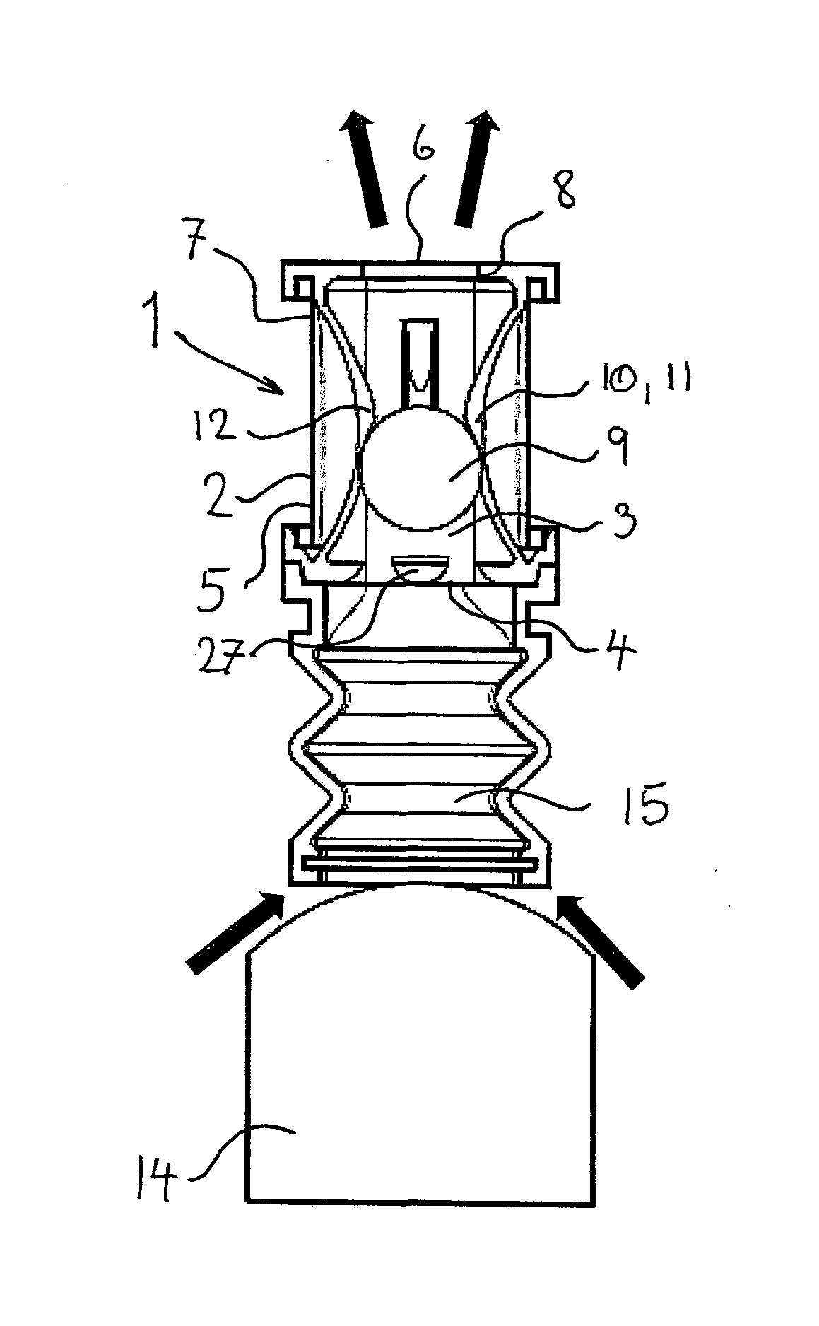
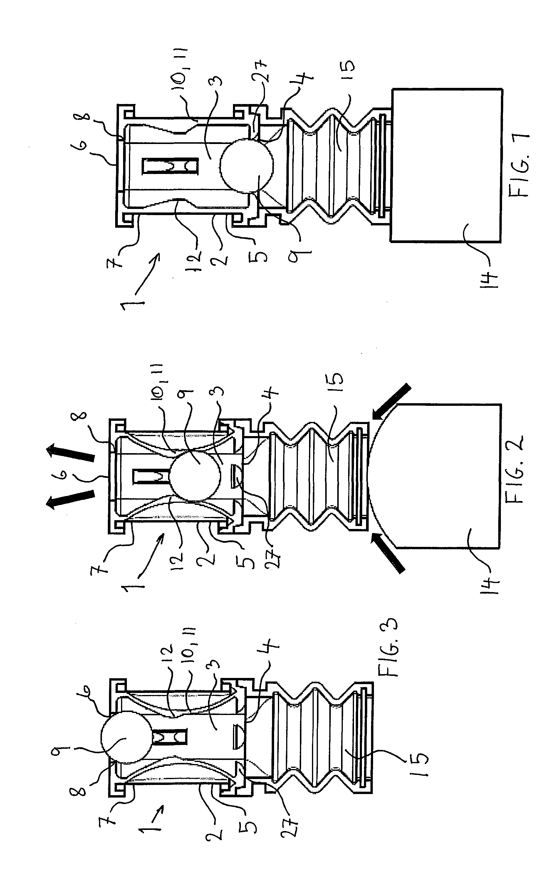
[0079]FIG. 1 illustrates a cross section through a flow blocking valve 1 connected to an engaged suction device 15 before vacuum is established, as seen from the side.

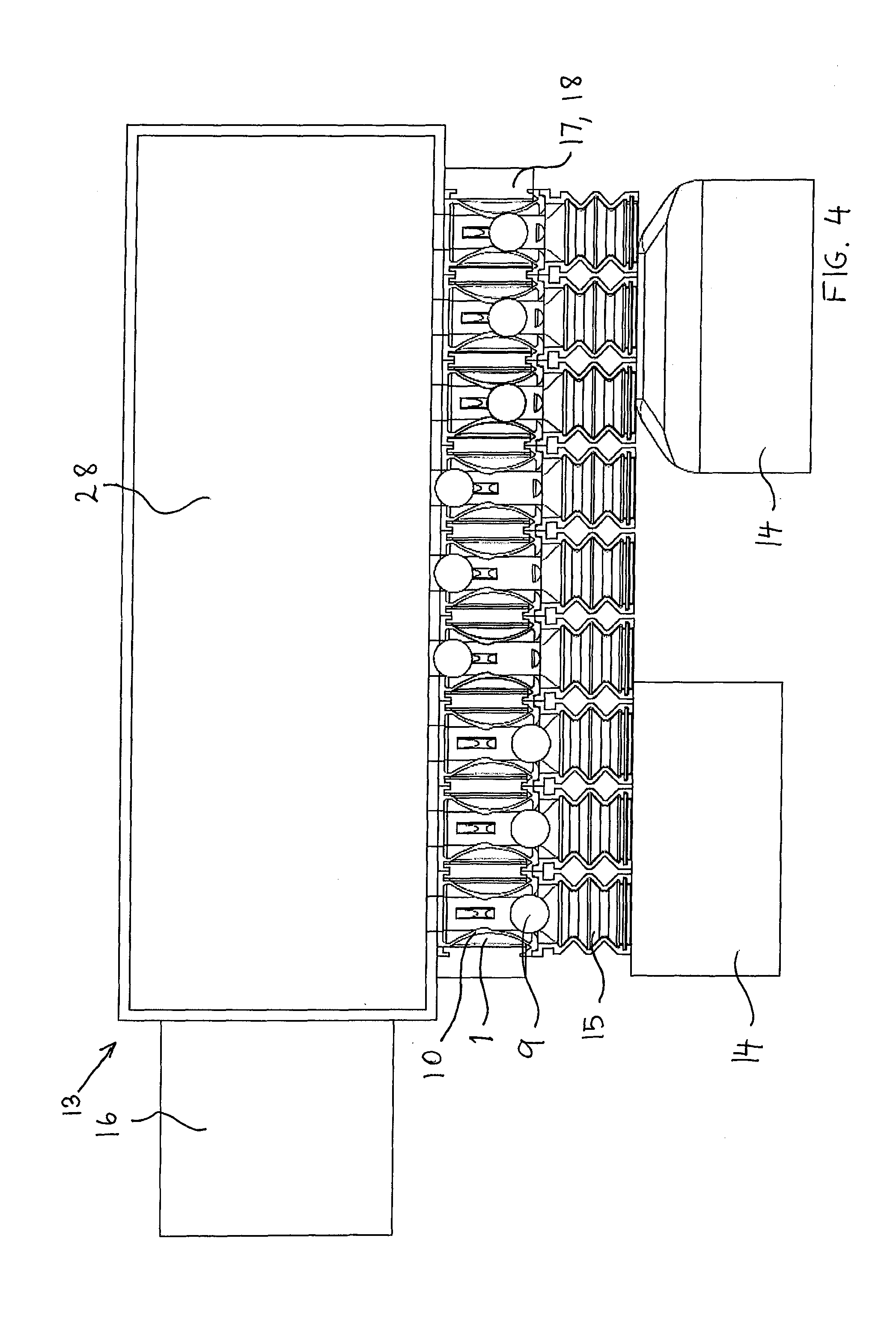
[0080]In this embodiment the flow blocking valve 1 is mounted directly onto a suction device 15 but in another embodiment the flow blocking valve 1 could be mounted separate from the device which flow it controls i.e. as a separate valve mounted on a hose or a pipe or it could be one of several valves mounted in a dedicated flow control cabinet.

[0081]In this embodiment the flow blocking valve 1 comprises a valve housing part 2 which in this embodiment constitutes substantially the entire valve house. However in another embodiment the valve housing part 2 would only constitute a part of the valve house. Further, the valve housing part 2 is hollow so that a flow duct 3 is formed between a flow inlet 4 and a flow outlet 6 arranged respectively at an inlet end 5 and an outlet end 7 of the flow duct 3.

[0082]A displaceable v...


PUM


Abstract

Disclosed is a flow blocking valve, a vacuum lifting device have such valve, a vacuum lifting arrangements, and methods for operating the same, the valve including a valve housing part forming a flow duct between a flow inlet arranged at an inlet end of the duct and a flow outlet arranged at an outlet end of the duct, where a seat is arranged at the flow outlet, the valve further including a displaceable valve blocking device arranged to move inside the flow duct, where said blocking device is arranged to block the flow through said valve when being forced against said seat, the valve also including obstruction means being displaceable in a direction substantially transverse in relation to a longitudinal direction of the flow duct, where the obstruction means is arranged to controllably obstruct the passage of the displaceable valve blocking device without completely disabling flow through the flow duct.

Description

FIELD OF THE INVENTION[0001]The invention relates to a flow blocking valve comprising a valve housing part forming a flow duct, a displaceable valve blocking device arranged to move inside the flow duct and obstruction means arranged to controllably obstruct the passage of the displaceable valve blocking device without completely disabling flow through the flow duct.[0002]The invention also relates to a vacuum lifting device for fixating goods by means of vacuum and a method for operating a vacuum lifting device.BACKGROUND OF THE INVENTION[0003]A vacuum lifting device is often used as a fixation tool e.g. when palletizing goods. The vacuum lifting device typically comprises an array of individual suction cups connected to a common vacuum pump so that when the lifting device is placed on an item and vacuum is established inside the suction cups, by means of the vacuum pump, the lifting device will be able to lift the item and move it around until it reaches its destination. Here the ...

Claims


Application Information

Patent Timeline
IPC IPC(8): B25J15/06F16K1/14F16K31/12
CPCB65G47/91B25J15/0616F16K31/12F16K1/14B25J15/0625
Inventor ANDERSEN, FINN, LYNGE, DAHL
Owner INVA INVEST HLDG APS
Why Eureka
Try Eureka