Intake manifold structure for engine

Active Publication Date: 2016-03-03
MAZDA MOTOR CORP
View PDF3 Cites 14 Cited by
  • Summary
  • Abstract
  • Description
  • Claims
  • Application Information

AI Technical Summary

Benefits of technology

[0006]In view of the above, an object of the present invention is to provide a structure of an intake manifold for an engine, which enable

Problems solved by technology

Extending the pipe to the position where purge gas is introduced on the outside of the intake manifold as described above, however, may increase the cost and the weight of the engine.
Th

Method used


Image

  • Intake manifold structure for engine
  • Intake manifold structure for engine
  • Intake manifold structure for engine

Examples


Embodiment Construction

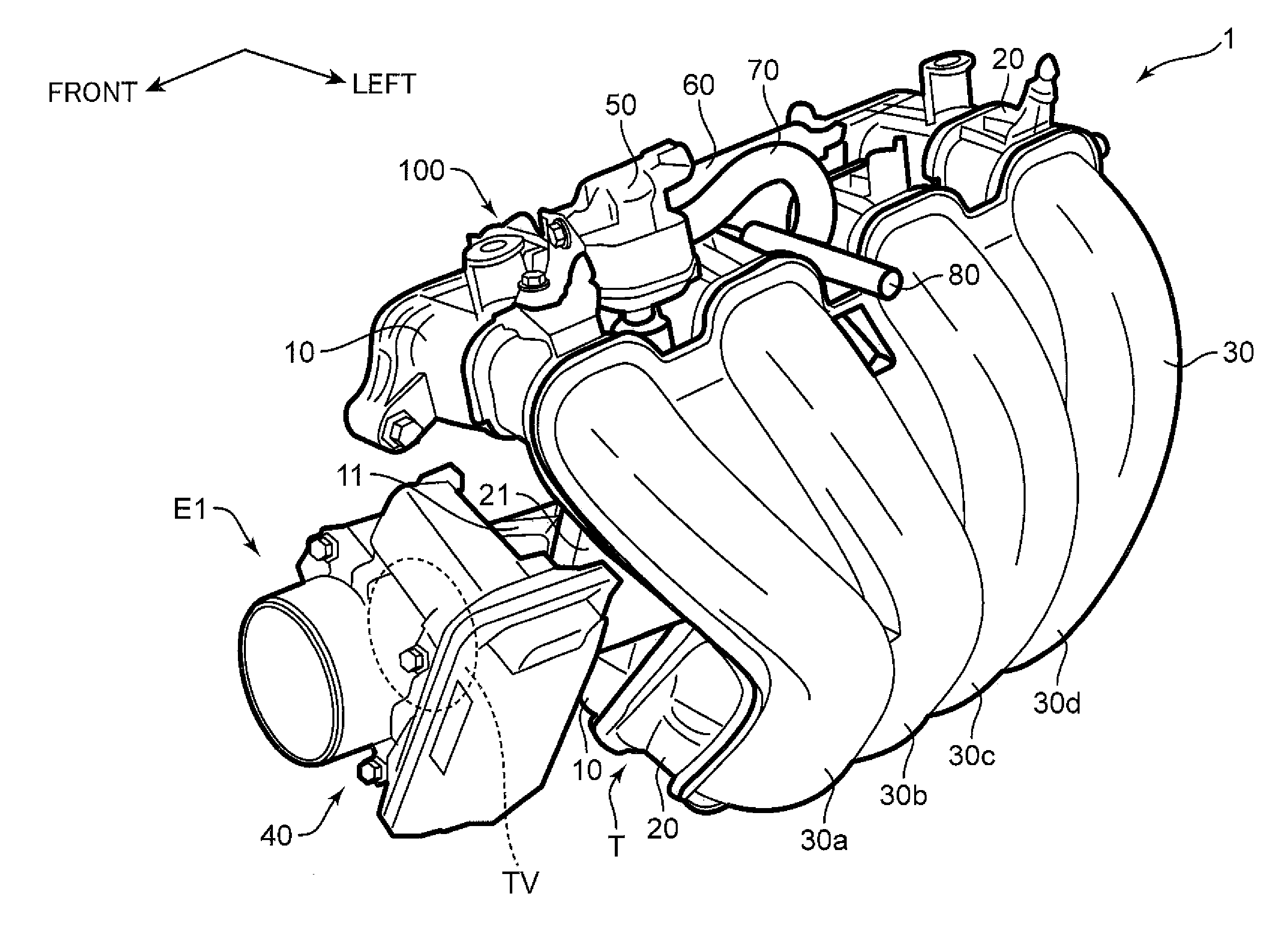
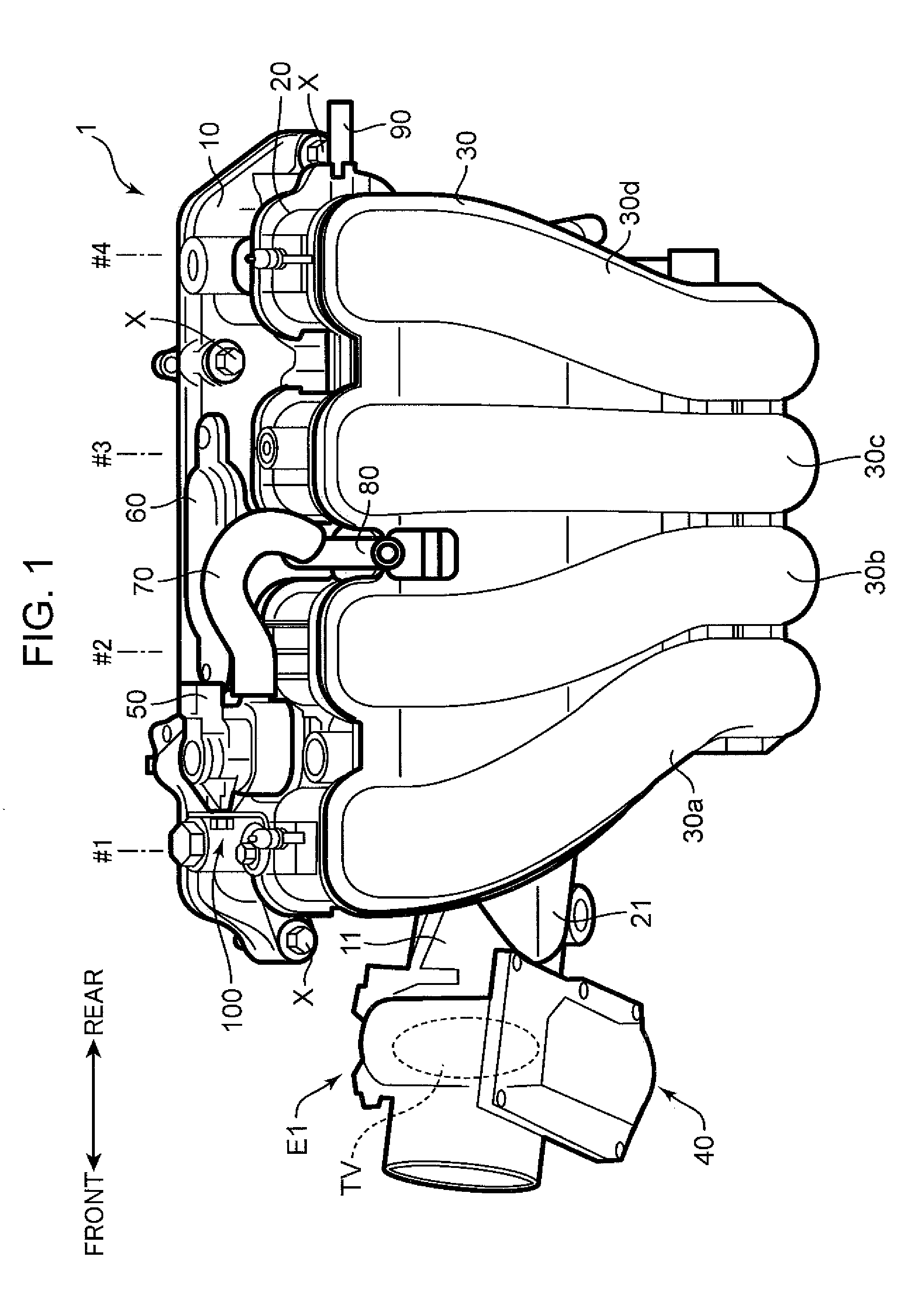
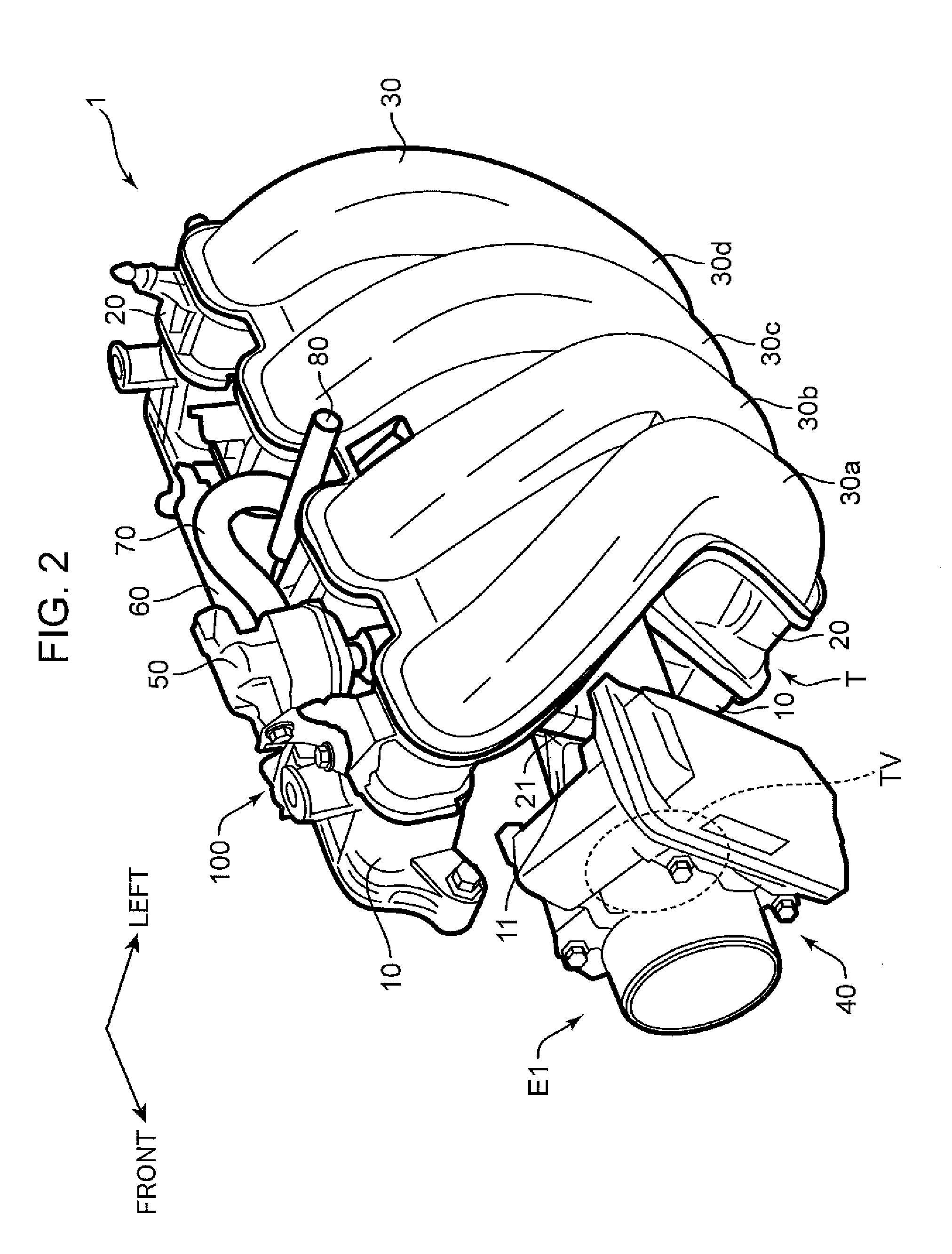
[0018]In the following, an embodiment of the invention is described referring to the drawings. In FIG. 1 to FIG. 9, front, rear, and left respectively indicate the vehicle front side, the vehicle rear side, and the vehicle left side. Further, in the embodiment, upstream and downstream each indicates the direction of gas flowing through a relevant portion.

[0019]First of all, the overall configuration of an intake manifold 1 for an engine in the embodiment is described.

[0020]The intake manifold 1 in the embodiment is constituted of three divided pieces 10, 20, and 30 (see FIG. 1). Each of the divided pieces 10, 20, and 30 is a resin molded part, and is integrally molded. The divided pieces 10, 20, and 30 are joined to each other by welding or adhesion. The intake manifold 1 is connected to an in-line 4-cylinder gasoline engine (not illustrated) via a gasket (not illustrated). Although not illustrated, the engine is disposed in a longitudinal posture such that the cylinder array direct...


PUM

PropertyMeasurementUnit
Structureaaaaaaaaaa

Abstract

A structure of an intake manifold (1) for an engine is constituted of divided pieces (10, 20, 30). The structure of the intake manifold includes a gas supply hole (53) formed in a predetermined position of an outer surface of the intake manifold, and configured to supply predetermined gas from the outside, and a gas inlet passage (51) formed in predetermined joint surfaces (10m, 20m) of the divided pieces (10, 20), and configured to guide the gas supplied through the gas supply hole to a predetermined gas inlet position (11) of an intake passage (E1).

Description

BACKGROUND OF THE INVENTION[0001]1. Field of the Invention[0002]The present invention relates to a structure of an intake manifold for an engine.[0003]2. Description of the Related Art[0004]In an engine to be loaded in an automobile or a like vehicle, fuel vapor generated in a fuel tank is introduced to an intake passage in order to prevent diffusion of fuel vapor into the air. Japanese Unexamined Patent Publication No. 2014-58879 discloses a configuration, in which a purge valve for regulating the amount of fuel vapor to be introduced to an intake passage is integrally mounted on an intake manifold, a pipe is provided between the purge valve and downstream of a throttle valve in the intake passage, and purge gas of fuel vapor is introduced from the purge valve to the intake passage via the pipe (particularly see FIG. 1 of the aforementioned publication).SUMMARY OF THE INVENTION[0005]Extending the pipe to the position where purge gas is introduced on the outside of the intake manifo...

Claims


Application Information

Patent Timeline
IPC IPC(8): F02M35/10F02M25/08F02M35/104
CPCF02M35/10222F02M35/104F02M25/0836F02M35/10301F02M35/10321F02M35/10065
Inventor TANAKA, FUSATOSHIKOJO, MIKIKOIWATA, KAZUOKIYOMIHARA, TATSUNORI
Owner MAZDA MOTOR CORP
Why Eureka
Try Eureka