Wave energy converter

Inactive Publication Date: 2016-03-03
POLYGEN
View PDF22 Cites 10 Cited by
  • Summary
  • Abstract
  • Description
  • Claims
  • Application Information

AI Technical Summary

Benefits of technology

[0014]The relative buoyancy of the spine and blades may be effective to support the blades in a desired orientation, and may be effective to support the

Problems solved by technology

The substantial energy present in ocean waves is largely unexploited, despite increasing global demand for renewable energy.
The resu

Method used


Image

  • Wave energy converter
  • Wave energy converter
  • Wave energy converter

Examples


Embodiment Construction

[0022]In order that the invention may be more clearly understood, embodiments thereof will now be described, by way of example only, with reference to the accompanying drawings, of which:

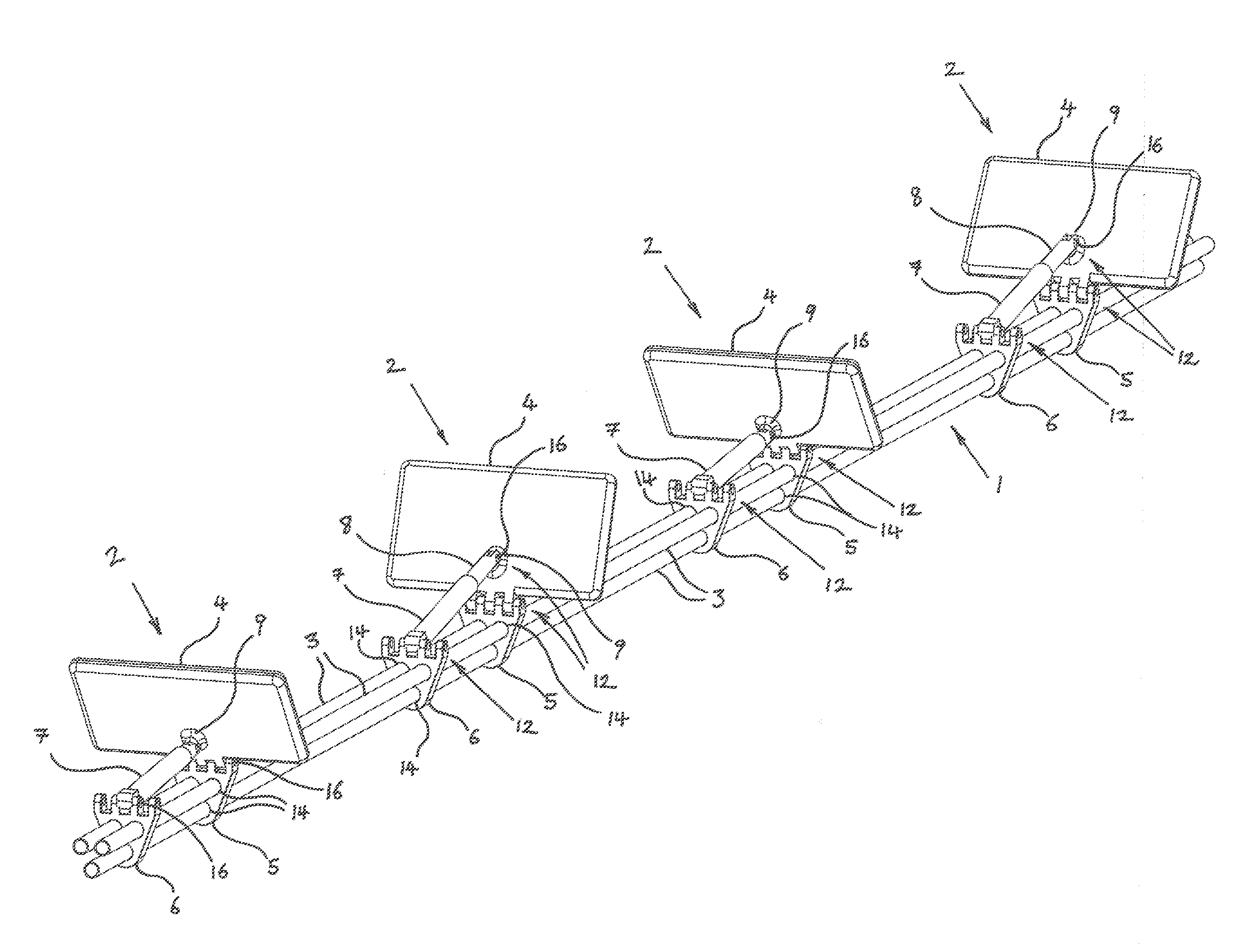
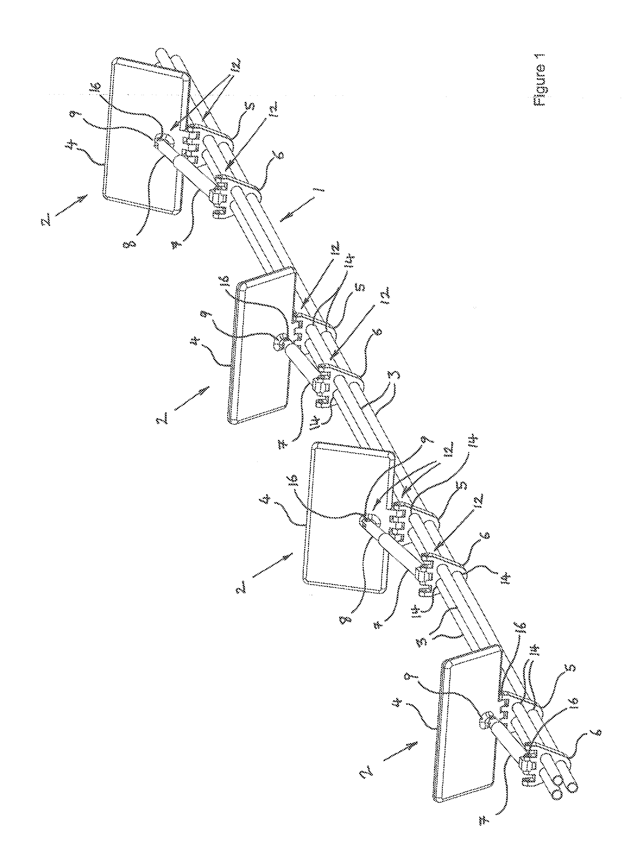
[0023]FIG. 1 is a perspective view of part of a wave energy converter according to an embodiment of the present invention;

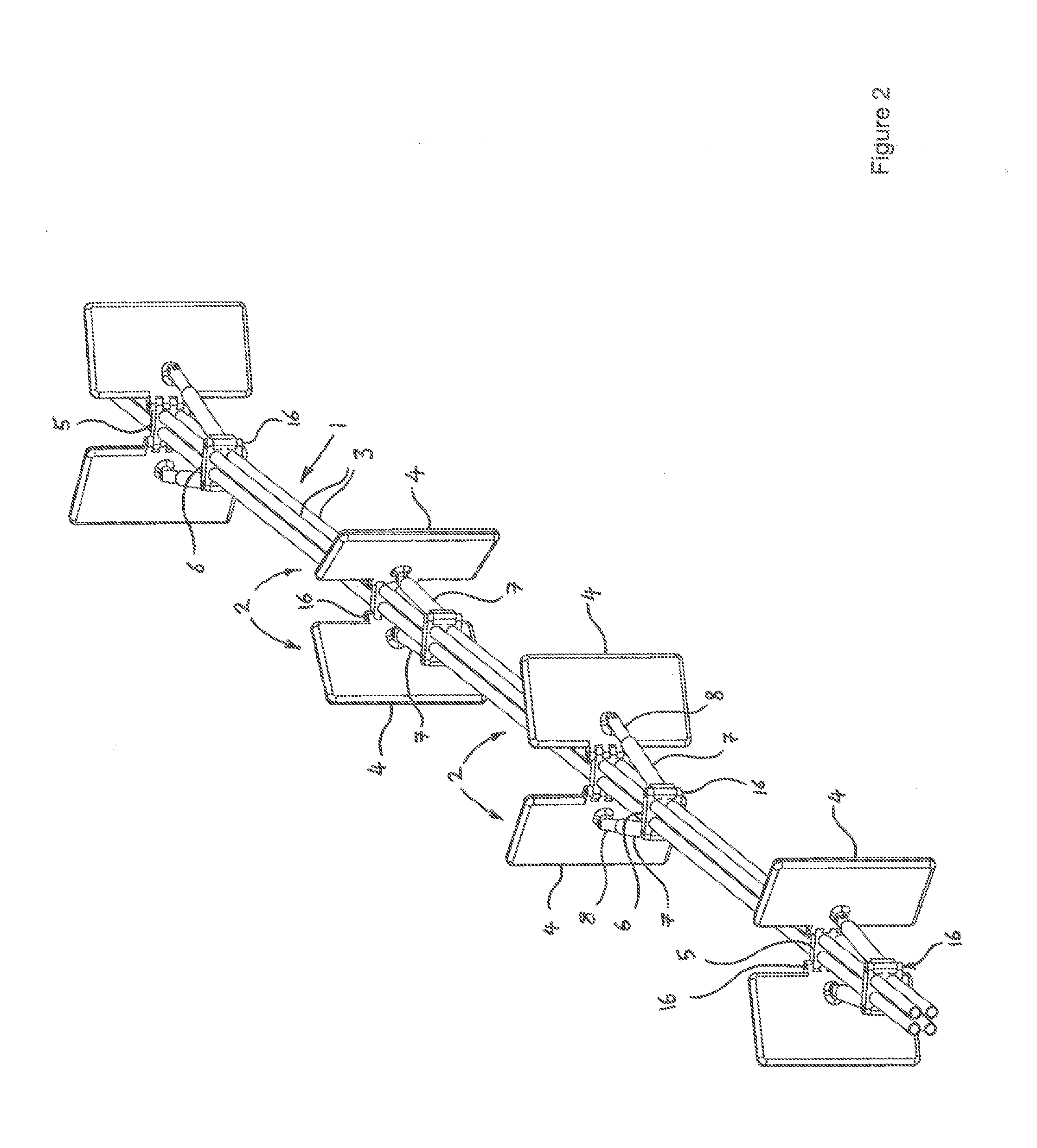
[0024]FIG. 2 is a perspective view of part of a wave energy converter according to another embodiment of the present invention;

[0025]FIG. 3 is a perspective view of part of a wave energy converter according to a further embodiment of the invention;

[0026]FIG. 4 is a perspective view of a wave energy converter according to an embodiment of the invention and comprising the part shown in FIG. 3;

[0027]FIG. 5 is a perspective view of a wave energy converter according to a further embodiment of the invention and also comprising the part shown in FIG. 3.

[0028]FIG. 6 is a perspective view of part of a wave energy converter forming yet another embodiment of the present invention; and

[0029]...


PUM


Abstract

A marine wave energy converter is described, comprising a flexible spine (1) and a plurality of blades (2) rotatably mounted on and supported by the spine. Each blade is operable, by ocean waves travelling parallel to the longitudinal axis of the spine, to angularly oscillate and thereby to drive the conversion of marine wave energy into useful work, such as into electrical energy. The spine (1) is resiliently flexible and comprises one or more elongate structural elements (3) and a plurality of connectors (5, 6) mounted along a continuous length thereof, wherein the/each elongate structural element (3) is a conduit. Each blade (2) is hingedly secured to the spine (1) at a said connector (5), so as to rotate about a hinge axis perpendicular to the longitudinal axis of the spine.

Description

TECHNICAL FIELD OF THE INVENTION[0001]The present invention relates to a marine wave energy converter.BACKGROUND TO THE INVENTION[0002]The substantial energy present in ocean waves is largely unexploited, despite increasing global demand for renewable energy. Traditional wave energy conversion systems are typically either mounted on the sea bed or supported near the ocean surface on a floating platform or by means of floats. Floating systems can capture the maximal energy wave motion occurring nearest to the ocean surface, but must typically be held in place by extremely strong moorings or on vertically sliding supports mounted on the sea bed. Such wave energy conversion systems and their moorings and / or mountings must therefore resist the often extreme loading of ocean waves and withstand the resulting large fluctuating stresses imparted to the structure, including high stress concentrations around mooring connectors and / or fixed mountings. Due to the complexity of repairing offsho...

Claims


Application Information

Patent Timeline
IPC IPC(8): F03B13/22
CPCF03B13/182F03B13/20F05B2240/93F03B13/22F05B2280/4003Y02E10/38F05B2270/18Y02E10/30
Inventor EAVIS, ROBERT
Owner POLYGEN
Why Eureka
Try Eureka