Gas turbine engines with plug resistant effusion cooling holes

a technology of gas turbine engines and effusion cooling holes, which is applied in the direction of machines/engines, stators, lighting and heating apparatus, etc., can solve the problems of small diameter effusion cooling holes that are susceptible to plugging and the difficulty of cooling remains

Inactive Publication Date: 2016-03-03
HONEYWELL INT INC
View PDF8 Cites 42 Cited by
  • Summary
  • Abstract
  • Description
  • Claims
  • Application Information

AI Technical Summary

Problems solved by technology

However, given the high temperature of engine operation, cooling remains a challenge.
As an example, the small diameter effusion cooling holes may be susceptible to plugging by particles within the engine air flow.

Method used


Image

  • Gas turbine engines with plug resistant effusion cooling holes
  • Gas turbine engines with plug resistant effusion cooling holes
  • Gas turbine engines with plug resistant effusion cooling holes

Examples


Embodiment Construction

[0016]The following detailed description is merely exemplary in nature and is not intended to limit the invention or the application and uses of the invention. Furthermore, there is no intention to be bound by any theory presented in the preceding background or the following detailed description.

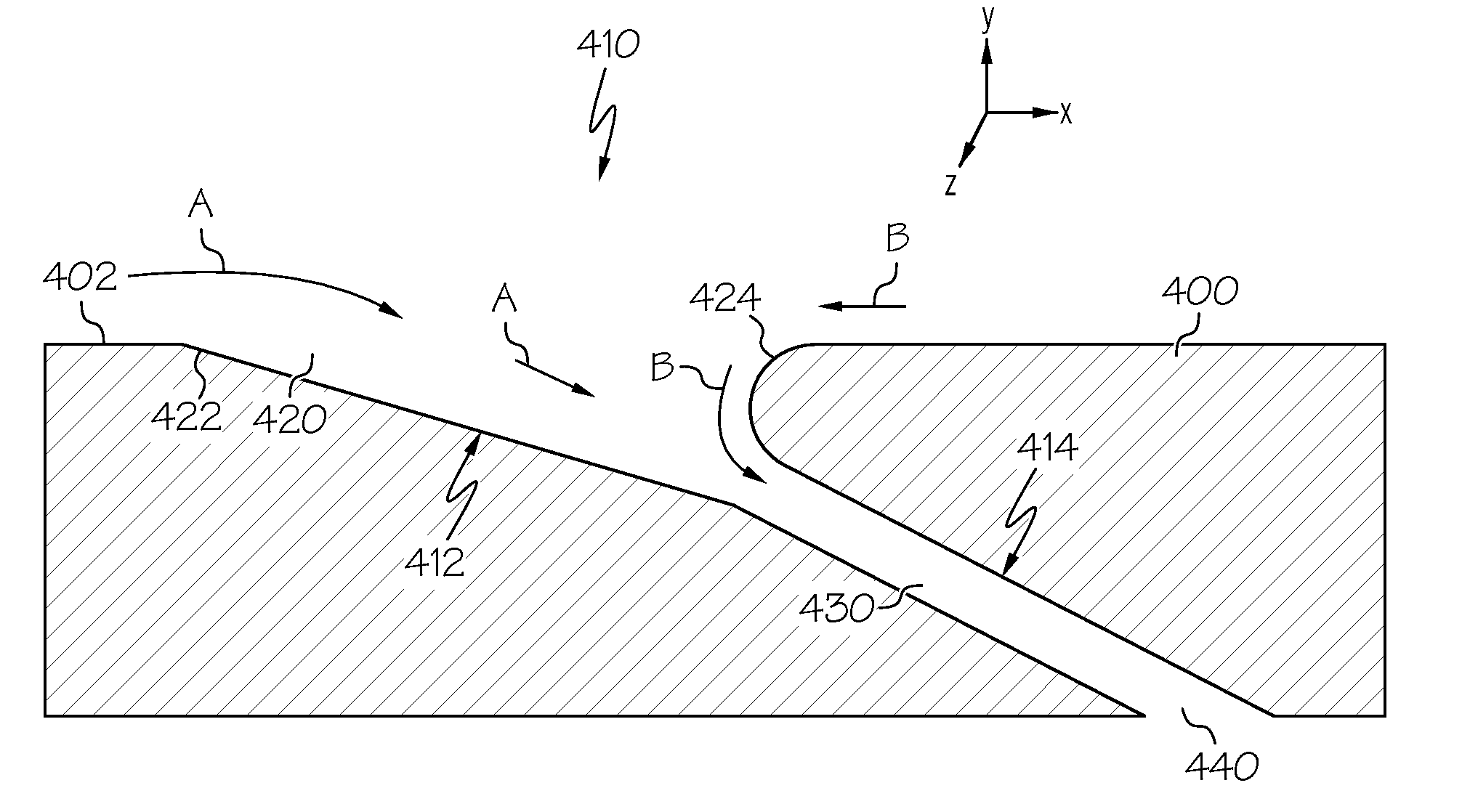
[0017]Broadly, exemplary embodiments discussed herein include gas turbine engines with combustors having improved effusion cooling. In one embodiment, the effusion cooling holes may have enlarged inlet portions and / or curved inlet edges relative to the metering sections. This may enable smoother flow into and through each effusion cooling hole to prevent or mitigate particles separating from the airflow and accumulating and blocking the hole, thereby enabling more efficient cooling and / or operation at higher temperatures.

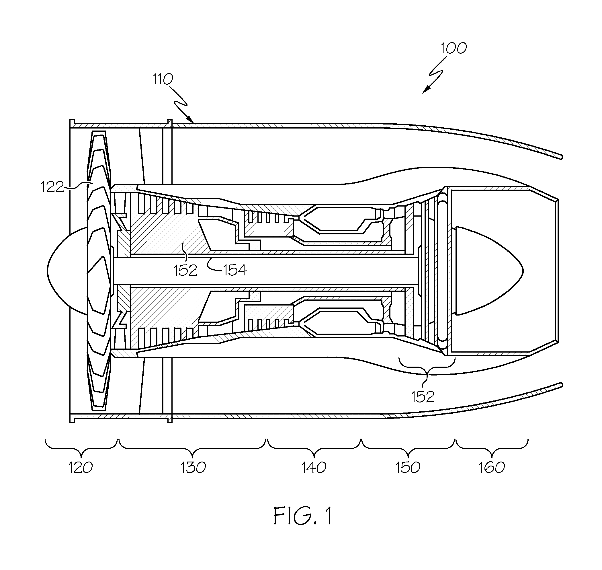
[0018]FIG. 1 is a simplified, cross-sectional view of a gas turbine engine 100 according to an embodiment. The engine 100 may be disposed in an engine case 110 and may inclu...


PUM


Abstract

A combustor for a turbine engine is provided. A first liner has a first surface and a second surface. A second liner forms a combustion chamber with the second side of the first liner, and the combustion chamber configured to receive an air-fuel mixture for combustion therein. The first liner defines a plurality of effusion cooling holes configured to form a film of cooling air on the second surface of the first liner. The plurality of effusion cooling holes includes a first effusion cooling hole extending from the first surface to the second surface and including an inlet portion extending from the first surface, a metering portion fluidly coupled to the inlet portion, and an outlet portion fluidly coupled to the metering portion and extending to the second surface. The inlet portion is larger than the metering portion.

Description

TECHNICAL FIELD[0001]The following discussion generally relates to gas turbine engine combustors, and more particularly, to combustors with improved effusion cooling holes.BACKGROUND[0002]A gas turbine engine may be used to power various types of vehicles and systems. A particular type of gas turbine engine that may be used to power aircraft is a turbofan gas turbine engine. A turbofan gas turbine engine may include, for example, five major sections: a fan section, a compressor section, a combustor section, a turbine section, and an exhaust section. The fan section is positioned at the front or inlet section of the engine and includes a fan that induces air from the surrounding environment into the engine and accelerates a fraction of this air toward the compressor section. The remaining fraction of air induced into the fan section is accelerated into and through a bypass plenum and out the exhaust section.[0003]The compressor section raises the pressure of the air received from the...

Claims


Application Information

Patent Timeline
Patent Type & Authority Applications(United States)
IPC IPC(8): F23R3/08F23R3/00
CPCF23R3/005F23R3/08F23R3/06Y02T50/60F01D5/186F01D9/023F05D2260/202F23R3/002F23R3/04F23R2900/03041F23R2900/03042
Inventor DUDEBOUT, RODOLPHEBLUMER, ERIC
Owner HONEYWELL INT INC
Why Eureka
Try Eureka