System for analysis of partial discharge defects of gas insulated switchgear

a technology of gas insulated switchgear and partial discharge defect, which is applied in the direction of measuring devices, testing dielectric strength, instruments, etc., can solve the problems of economic loss, etc., power loss, irreversible physical or chemical change of insulating material,

Inactive Publication Date: 2016-03-03
LSIS CO LTD
View PDF0 Cites 5 Cited by
  • Summary
  • Abstract
  • Description
  • Claims
  • Application Information

AI Technical Summary

Benefits of technology

[0020]Therefore, an aspect of the detailed description is to provide a system for analysis of partial discharge defects of a gas insulated switchgear, capable of precisely analyzing a defect of the gas insulated switchgear due to a partial discharge, by providing both partial discharge signal information on a partial discharge signal sensed by a detecting sensor, and detection signal information on a detection signal sensed by one or more neighboring sensors adjacent to the detecting sensor, to a monitor.

Problems solved by technology

However, despite such an excellent insulating property of the gas insulated switchgear, when an insulation accident occurs on a power system, a social confusion, an economical loss, etc. may be caused.
The partial discharge may cause power loss due to power leakage.
In some cases, the partial discharge may cause an irreversible physical or chemical change on an insulating material.
This may cause complete cutoff of power supply through a distribution line, or explosion of equipment.
This may cause a difficulty in precisely diagnosing whether a defect of the switchgear exists on a position where a partial discharge has occurred, and a cause of the occurrence of the defect.

Method used


Image

  • System for analysis of partial discharge defects of gas insulated switchgear
  • System for analysis of partial discharge defects of gas insulated switchgear
  • System for analysis of partial discharge defects of gas insulated switchgear

Examples


first embodiment

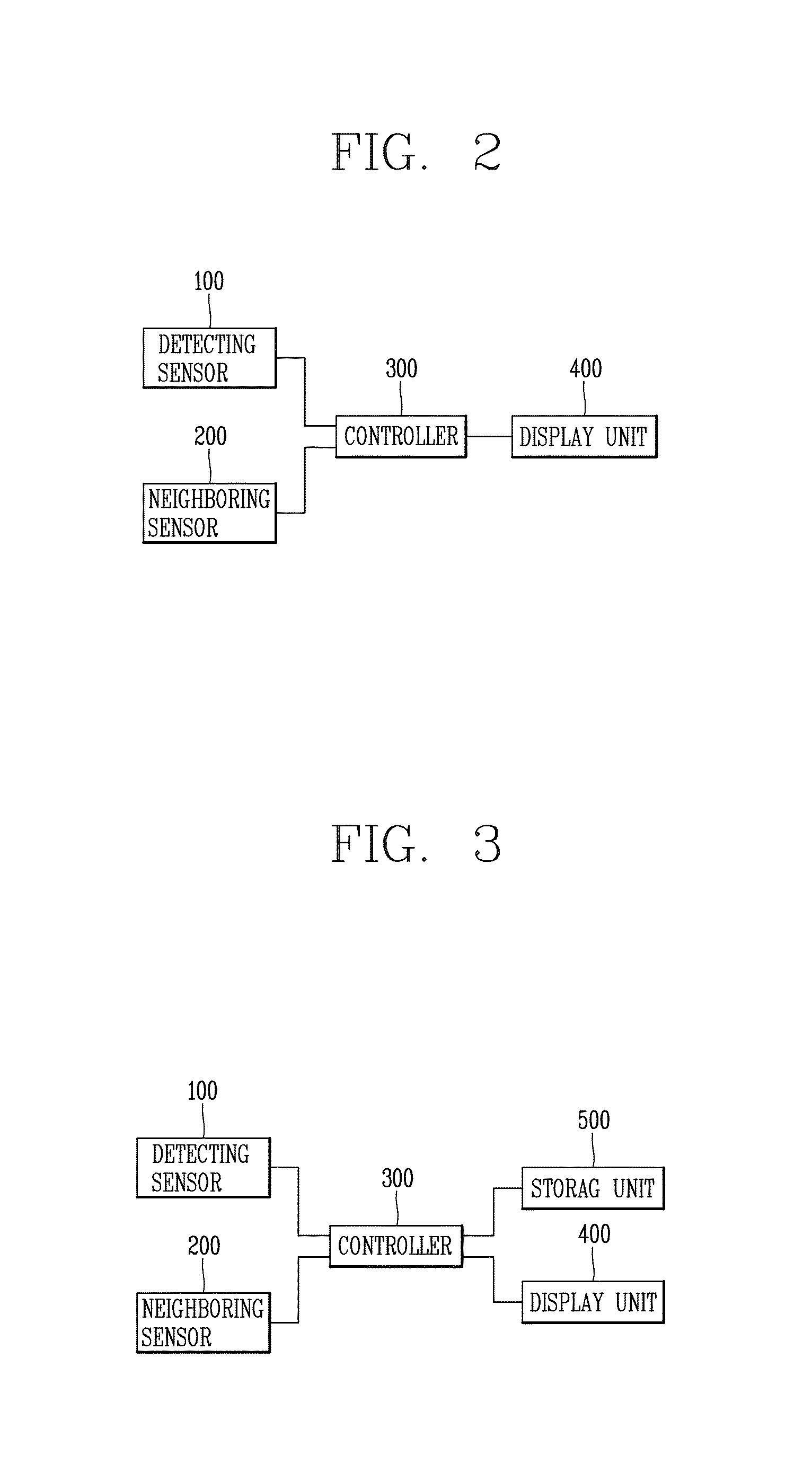
[0040]As shown in FIG. 2, the system for analysis of partial discharge defects of a gas insulated switchgear according to the present invention includes a detecting sensor 100, a neighboring sensor 200, a controller 300 and a display unit 400.

[0041]The detecting sensor 100 is attached to a specific position inside a gas insulated switchgear, and is configured to sense a partial discharge signal generated from the gas insulated switchgear. And the detecting sensor 100 is configured to detect a current pulse signal due to a partial discharge, or detect an ultrasonic signal due to a partial discharge.

[0042]The detecting sensor 100 is implemented as one of a UFH sensor, a VHF sensor, an HF sensor, an ultrasonic sensor and a TEV sensor. But the present invention is not limited to this, and various sensors may be used as the detecting sensor 100.

[0043]The neighboring sensor 200 is arranged near the detecting sensor 100 in one or more in number, and detects a signal generated from the peri...

second embodiment

[0060]As shown in FIG. 6, in a method for analyzing partial discharge defects of a gas insulated switchgear if a partial discharge charge amount and the number of times of partial discharges are more than a reference value, detection signal information of the neighboring sensors 200 on the partial discharge charge amount and the number of partial discharges more than the reference value is additionally stored.

[0061]That is, like in the method for analyzing partial discharge defects of a gas insulated switchgear according to the first embodiment, in the method for analyzing partial discharge defects of a gas insulated switchgear according to the second embodiment, it is determined whether a partial discharge signal has occurred or not (S201). Then, a partial discharge charge amount and the number of times of partial discharges are calculated with respect to a detection signal sensed by the neighboring sensors 200, and it is determined whether the calculated partial discharge charge ...


PUM


Abstract

The present invention relates to a system for analysis of partial discharge defects of a gas insulated switchgear capable of allowing a user to precisely analyze a defect of a gas insulated switchgear due to a partial discharge, by providing both partial discharge signal information on a partial discharge signal sensed by a detecting sensor, and detection signal information on a detection signal sensed by one or more neighboring sensors adjacent to the detecting sensor, to a monitor.

Description

CROSS-REFERENCE TO RELATED APPLICATION[0001]Pursuant to 35 U.S.C. §119(a), this application claims the benefit of earlier filing date and right of priority to Korean Patent Application No. 10-2014-0114380, filed on Aug. 29, 2014, the contents of which is incorporated by reference herein in its entirety.BACKGROUND OF THE INVENTION[0002]1. Field of the Invention[0003]The present invention relates to a system for analysis of partial discharge defects of a gas insulated switchgear, and more particularly, to a system for analysis of partial discharge defects of a gas insulated switchgear capable of allowing a user to precisely analyze a defect of a gas insulated switchgear due to a partial discharge, by providing both partial discharge signal information on a partial discharge signal sensed by a detecting sensor, and detection signal information on a detection signal sensed by one or more neighboring sensors adjacent to the detecting sensor, to a monitor.[0004]2. Background of the Invent...

Claims


Application Information

Patent Timeline
Patent Type & Authority Applications(United States)
IPC IPC(8): G01R31/327G01R31/12
CPCG01R31/12G01R31/327G01R31/14G01R31/1254G01R31/3274
Inventor KWON, HYUN, HOLEE, DO, HOONLEE, JIN, HOJIN, CHANG, HWAN
Owner LSIS CO LTD
Why Eureka
Try Eureka