Numerical control device

a control device and numerical technology, applied in the direction of electric programme control, program control, instruments, etc., can solve the problems of increasing the cycle time, affecting the machining tool, and not reaching the commanded reversing point,

Active Publication Date: 2016-03-03
FANUC LTD
View PDF3 Cites 1 Cited by
  • Summary
  • Abstract
  • Description
  • Claims
  • Application Information

AI Technical Summary

Benefits of technology

[0013]The present invention, with the configuration described above, can provide a numerical control device which enables arriving the commanded reversing point while minimizing cycle time under a command for reversing the feed shaft movement.

Problems solved by technology

In velocity control of a feed shaft of a machining tool, instant output of velocity signal commanded by the program generates rapid acceleration and rapid time derivative of acceleration (hereinafter referred to as “jerk”) to cause a large amount of impact and machining error for the machining tool.
The filtering of acceleration / deceleration, when change of movement direction of the feed shaft generates a reversal in the machining path as described above, brings a problem that the path does not reach a commanded reversing point.
However, there is a problem that, re-acceleration time, needed when the acceleration is set to be 0 by filtering the acceleration / deceleration, increases the cycle time.

Method used


Image

  • Numerical control device
  • Numerical control device
  • Numerical control device

Examples


Embodiment Construction

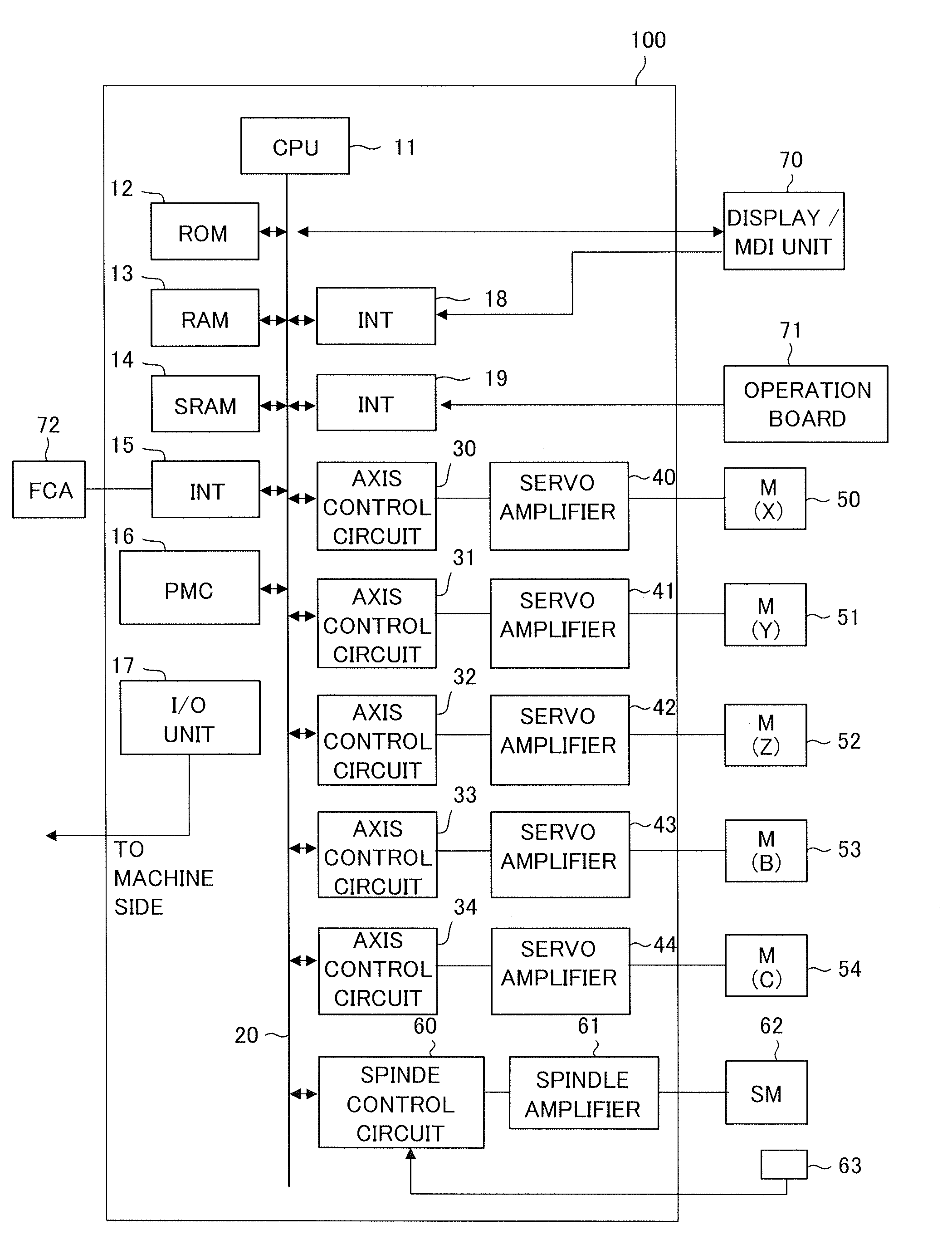
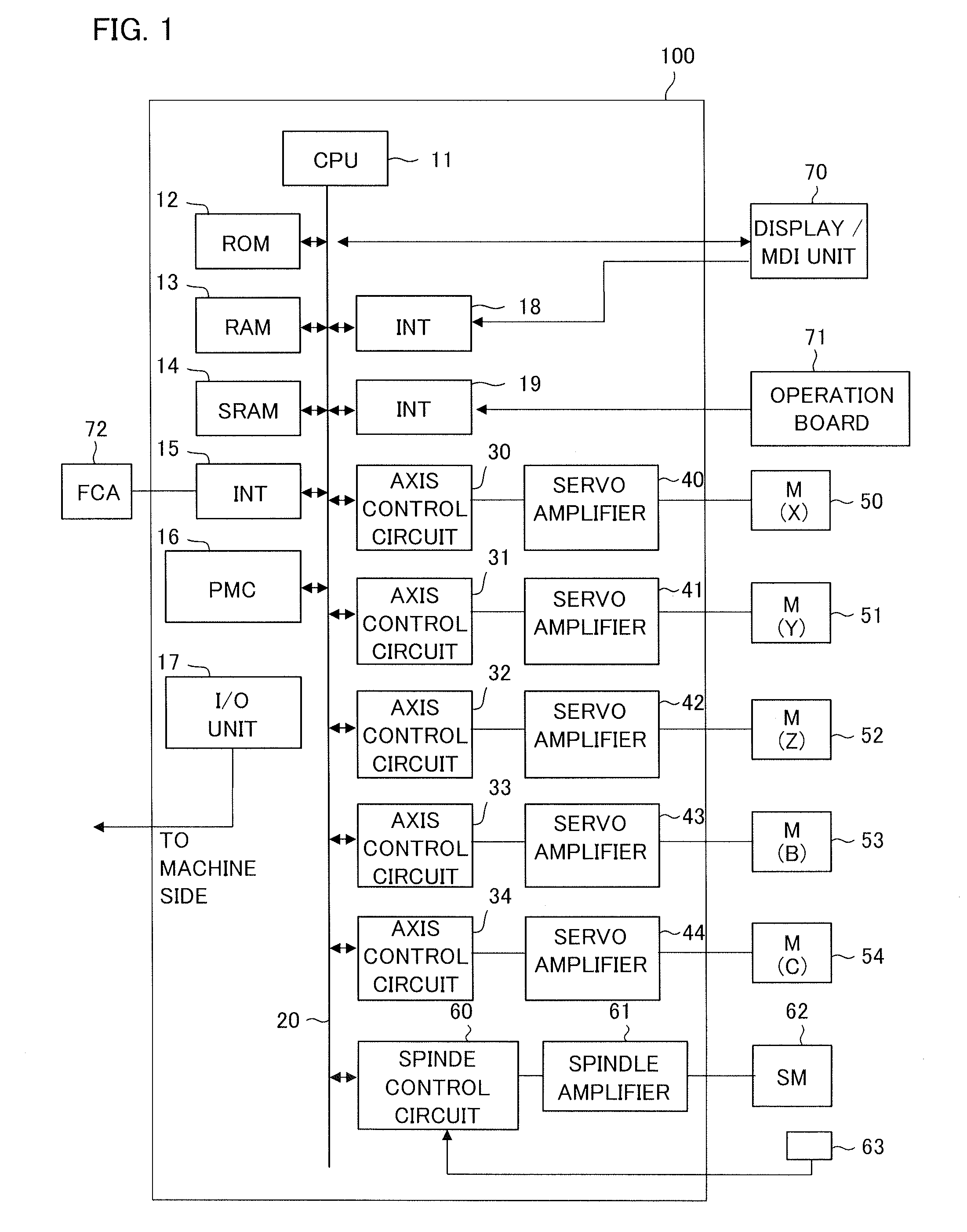
[0021]FIG. 1 is a block diagram showing a numerical control device (CNC) 100 according to an embodiment of the present invention. A CPU 11 is a processor which control whole numerical control device 100. The CPU 11 reads out a system program stored in a ROM 12 via a bus 20, and controls whole numerical control device according to the system program. A RAM 13 stores temporary calculation data, display data, and various kinds of data input by an operator via a display / MDI unit 70.

[0022]A SRAM 14, backed up by a not-shown battery, is configured to be a non-volatile memory which holds a storage state even when a power source of the numerical control device 100 is turned off. The SRAM 14 stores a machining program read in via an interface 15, a machining program input via the display / MDI unit 70, and the like. Various kinds of system programs for executing process for edition mode, which is necessary for generating and editing a machining program, and process for automatic operation are ...


PUM


Abstract

A numerical control device includes a command analysis unit, an acceleration calculation unit in reversing operation, a velocity control unit, and an interpolation unit. The acceleration calculation unit in reversing operation is configured to calculate the acceleration of the drive shaft before and after the reversing operation when reversal of the commanded path of the drive shaft based on the commanded data is detected by the velocity control unit.

Description

BACKGROUND OF THE INVENTION[0001]1. Field of the Invention[0002]The present invention relates to a numerical control device, and particularly to the numerical control device for calculating optimum acceleration in reverse operation.[0003]2. Description of the Related Art[0004]In velocity control of a feed shaft of a machining tool, instant output of velocity signal commanded by the program generates rapid acceleration and rapid time derivative of acceleration (hereinafter referred to as “jerk”) to cause a large amount of impact and machining error for the machining tool. Japanese Patent Laid-Open No. 59-062909 discloses a technique in which acceleration and jerk is suppressed by filtering acceleration / deceleration, to avoid a great impact on the machining tool. The technique for control, described above, effectively suppress the impact on the machining tool when change of moving direction of the feed shaft generates a corner in a machining path.[0005]The technique descried in Japane...

Claims


Application Information

Patent Timeline
Patent Type & Authority Applications(United States)
IPC IPC(8): G05B19/19
CPCG05B19/19G05B2219/34179G05B2219/41408G05B19/416G05B2219/43001
Inventor WATANABE, MITSUNORIONO, TAKENORI
Owner FANUC LTD
Why Eureka
Try Eureka