Solid-wall scroll centrifuge having an energy recovery device

a technology of energy recovery device and solid-wall scroll centrifuge, which is applied in the direction of centrifuges, rotary centrifuges, etc., can solve the problems of losing a portion of energy content, and achieve the effects of increasing the potential energy of the product discharged, producing especially favorably, and being easy to reconstruct technically

Active Publication Date: 2016-03-10
FLOTTWEG GMBH & CO KGAA
View PDF3 Cites 6 Cited by
  • Summary
  • Abstract
  • Description
  • Claims
  • Application Information

AI Technical Summary

Benefits of technology

[0011]In the case of such a solid-bowl screw centrifuge, the centrifuge drum may advantageously be equipped so that it can rotate in two opposing directions. With the discharge pipe, the clarified product discharged is preferably deflected in the direction opposite the respective direction of rotation of the centrifuge drum. The energy recovery device according to the invention may also be designed with two active surfaces as the discharge pipe, one active surface of which manifests an effect in the first direction of rotation and the second direction of rotation manifests its effect in the second direction of rotation.
[0012]In the case of the solid-bowl screw centrifuge according to the invention, the discharge pipe is advantageously designed with at least one section having an essentially straight flow path, which is set at an inclination to the longitudinal axis of the centrifuge drum at an angle between 45° and 85°, preferably between 55° and 65°. The discharge pipe according to the invention also preferably has at least one section with an essentially straight flow path, which is set at an inclination radially toward the inside by an angle of 4° to 28°, preferably 8° to the tangential direction at the discharge opening. The bottom surface of such a section is especially advantageously designed to be flat for at least a portion and/or to be largely flat. Such a bottom surface can be produced especially favorably in terms of the manufacturing technology. In addition, the product discharged thereon experiences a uniform acceleration over a longer distance, so it is comparatively easy to reconstruct technically by modeling. The acceleration leads to an increased conversion of the centrifugal momentum into a kinetic momentum directed tangentially. As a particularly large component of the centrifugal energy, it is converted into a tangentially directed drive energy. The planar section of the bottom surface is especially preferably inclined radially inward by an angle of 4° to 28°, preferably 8° to the tangential direction. Such an alignment of the deflected product stream causes deceleration of the outgoing product, which is predefined in a targeted manner in comparison with a purely tangential flow and this leads to a precisely predetermined stagnation effect. This stagnation leads to an increase in the potential energy of the product discharged and thus an improved subsequent conversion into tangential kinetic energy.
[0013]Furthermore, the discharge pipe according to the invention preferably has a discharge mouth wit

Problems solved by technology

Otherwise the air on the outside of the centrifuge drum, which is rotating at a high speed, will have a substantial

Method used


Image

  • Solid-wall scroll centrifuge having an energy recovery device
  • Solid-wall scroll centrifuge having an energy recovery device
  • Solid-wall scroll centrifuge having an energy recovery device

Examples


Embodiment Construction

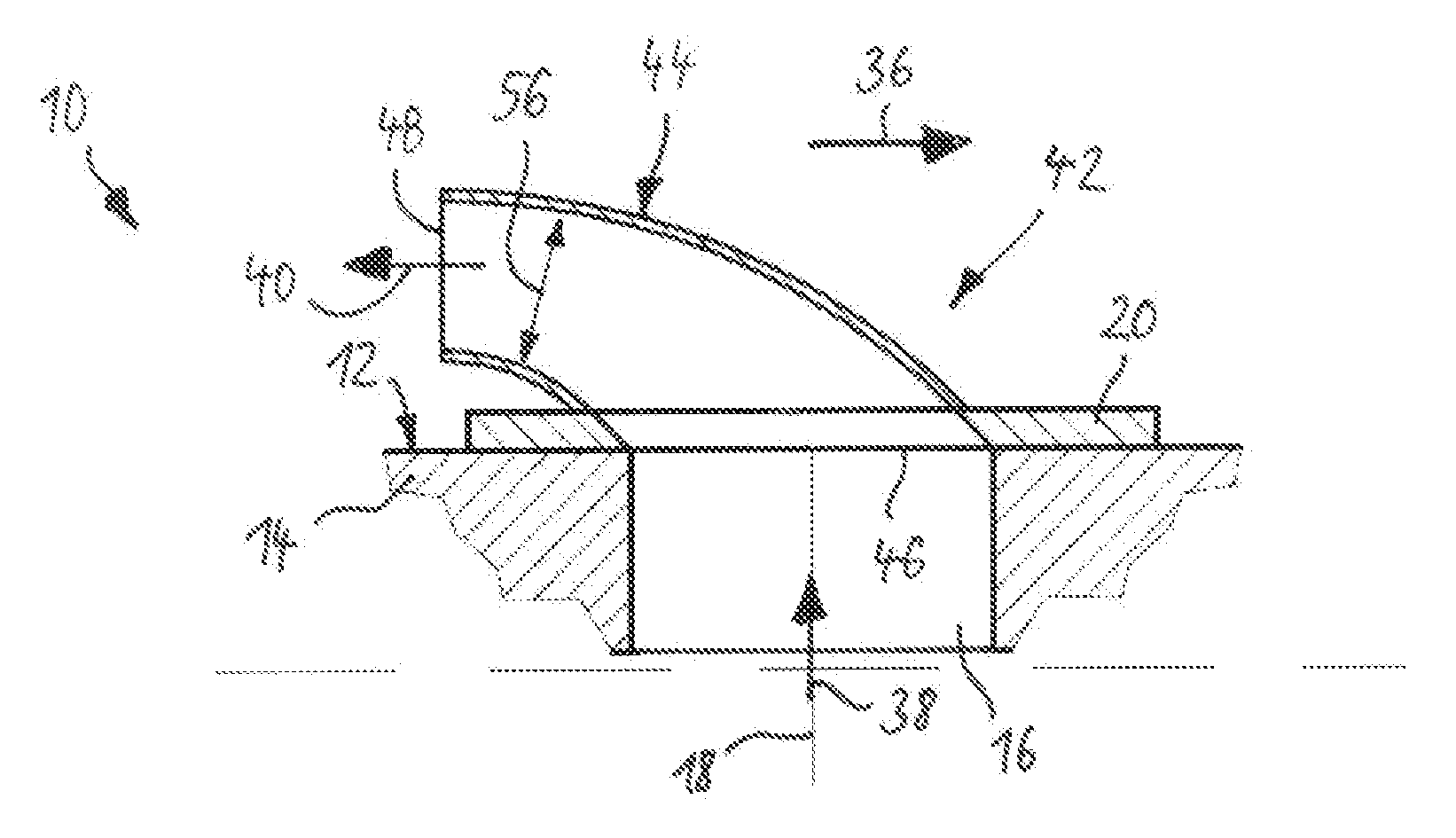
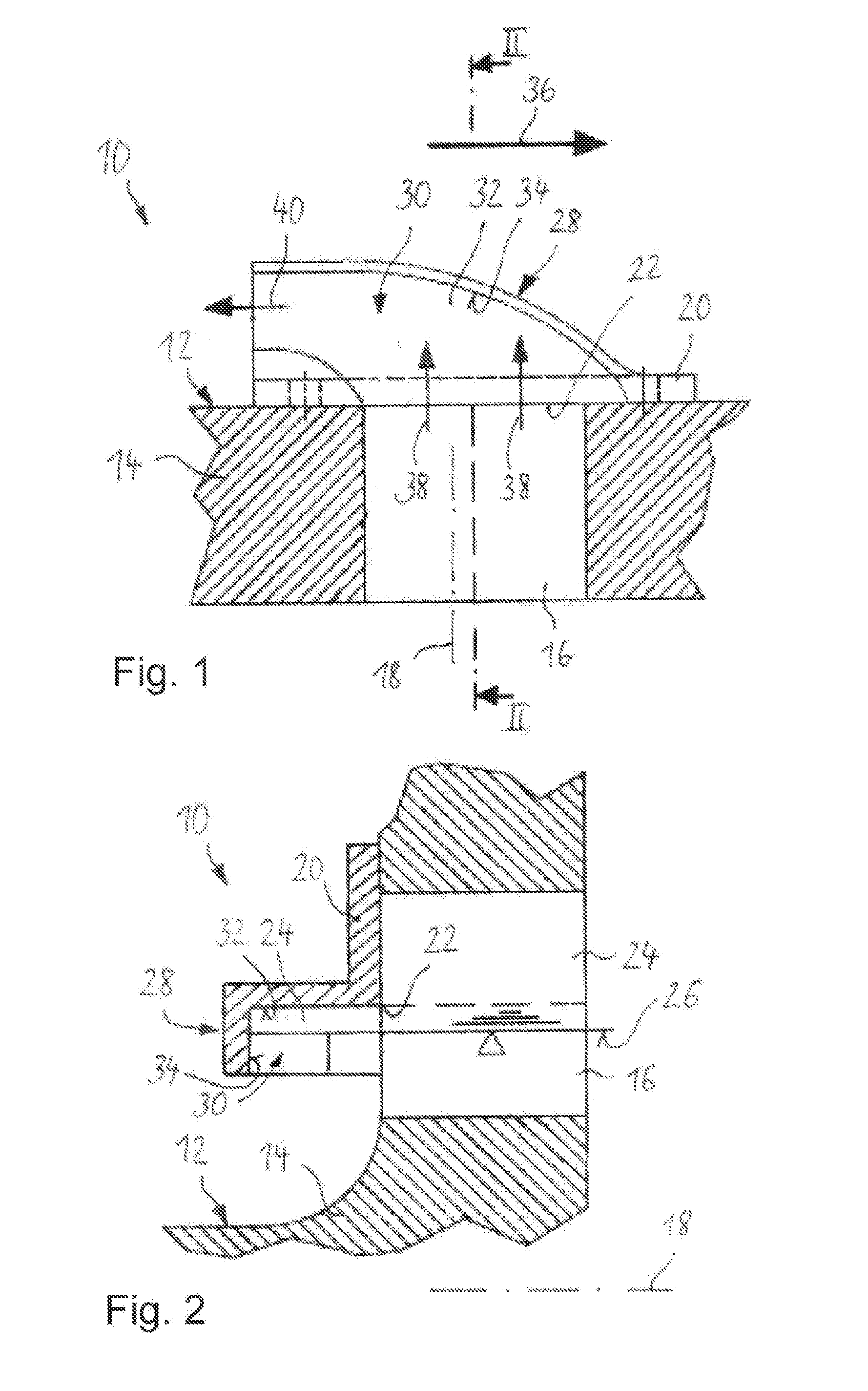
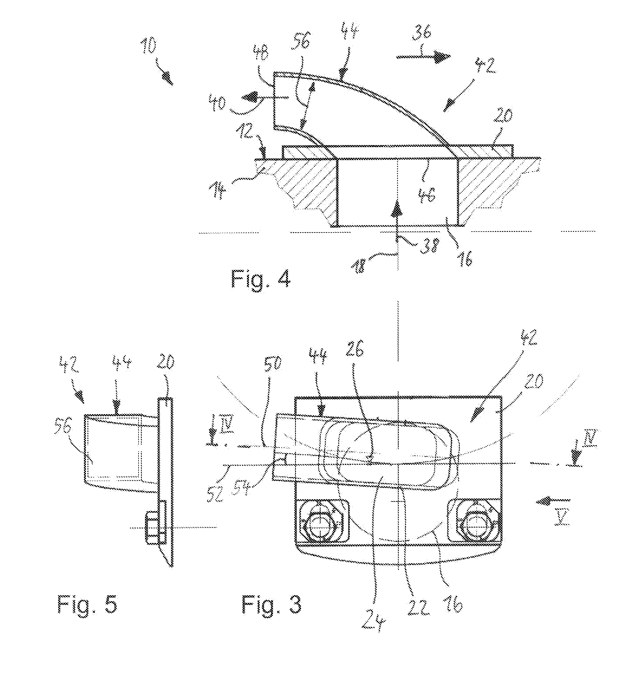
[0039]FIGS. 1 and 2 show the centrifuge drum 12 of a solid-bowl screw centrifuge 10 with its front end, i.e., front wall 14. On the front wall 14 can be seen one of several discharge openings 16 passing axially through the front wall 14 in the direction of a longitudinal axis 18 of the centrifuge drum 12. On the outside in front of the discharge opening 16, a weir gate 20 is in a stationary mount on the front wall 14, where it is adjustable. The weir gate 20 protrudes to just in front of the discharge opening 16, so that it covers the latter on the outside on its radially outer region. The weir gate 20 has a weir edge 22 on its radially inward facing border. According to the prior art, such a weir edge 22 extends along the front wall 14 and thus across the longitudinal axis 18. The weir edge 22 retains clarified product 24 in the centrifuge drum 12, so that during operation of the solid-bowl screw centrifuge 10, this clarified product 24 collects there with a pond depth 26 and then ...


PUM


Abstract

A solid-bowl screw centrifuge with a centrifuge drum that can rotate about a longitudinal axis during operation is created, at least one discharge opening being provided on the front wall thereof for clarified product to flow out of the centrifuge drum, a weir edge delimiting the discharge opening toward the outside radially and an energy recovery device for recovering energy from the clarified product being designed therewith. The energy recovery device is designed as a discharge pipe, which is located on the outside in front of the discharge opening and through which clarified product passes as it is discharged.

Description

BACKGROUND[0001]1. Field of the Invention[0002]The invention relates to a solid-bowl screw centrifuge with a centrifuge drum, which can be rotated about a longitudinal axis during operation, on whose front side are embodied at least one discharge opening for allowing clarified product to flow out of the centrifuge drum, a weir gate bordering the discharge opening toward the outside radially and an energy recovery device for recovering energy from the clarified product discharged. Furthermore, the invention also relates to one such energy recovery device for mounting on a front wall of a centrifuge drum.[0003]2. Description of the Related Art[0004]It is known in general that a plurality of discharge openings may be provided on the front wall of the centrifuge drum of a generic solid-bowl screw centrifuge, so that the clarified product can flow out through the opening by way of a respective weir gate. The weir edge forms the radially inner edge of a respective weir gate, which is moun...

Claims


Application Information

Patent Timeline
IPC IPC(8): B04B1/20
CPCB04B1/20B04B2001/2075B04B2001/2083
Inventor SCHLARB, MANFRED
Owner FLOTTWEG GMBH & CO KGAA
Why Eureka
Try Eureka