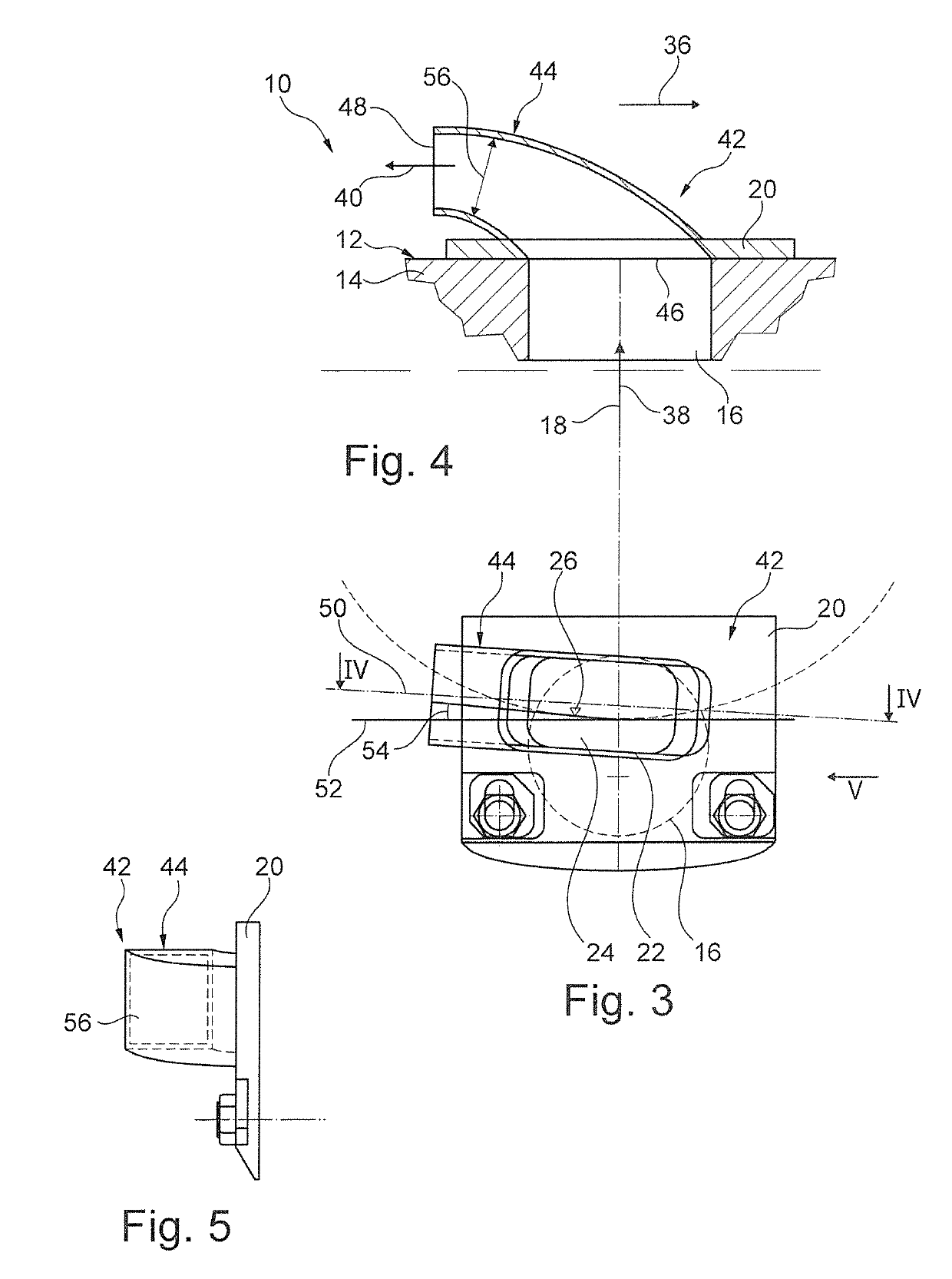
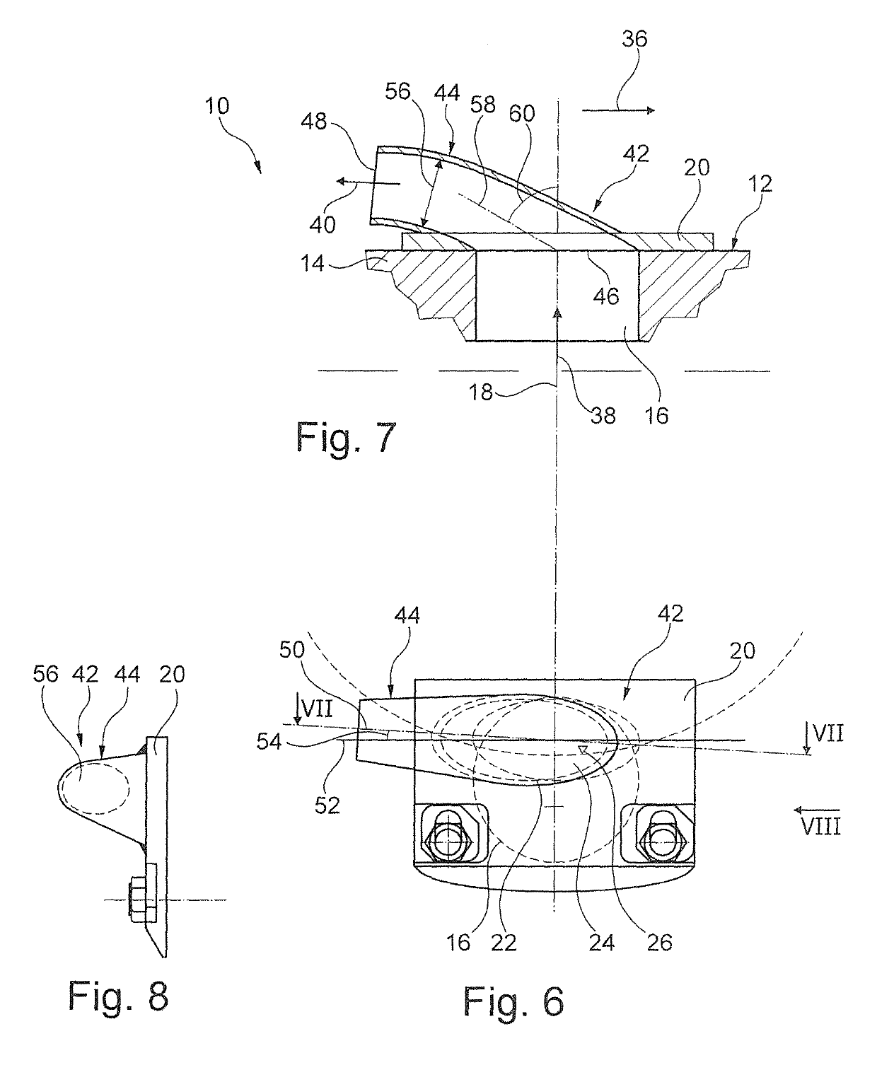
[0008]The approach according to the invention is based on the finding that the energy recovery effect of energy recovery devices of the aforementioned type is based in particular on this energy recovery device being closed on the inside radially. With this design, the product discharged through the energy recovery device is protected from external aerodynamic influences within the energy recovery device. Otherwise the air on the outside of the centrifuge drum, which is rotating at a high speed, will have a substantial influence on the product discharged, so that it loses a portion of its energy content due to friction with this air. This energy loss is prevented with the approach according to the invention, so that more energy can be recovered from the product discharged out of the device. With the approach according to the invention, the product discharged can be deflected from the axial direction essentially into the tangential direction in a particularly homogeneous and targeted manner. At the same time, energy losses occurring due to the diversion of the product discharged in the radial direction can be prevented. When using the discharge pipe according to the invention, the product discharged is held largely at the radius of the respective weir edge during the deflection, the discharge pipe being arranged on the outside axially in front of the discharge opening, so that even minor changes in the radius of the flow path may be advantageous, as will be explained below.
[0010]In the case of the solid-bowl screw centrifuge according to the invention, the discharge pipe is advantageously designed with at least one section having an essentially straight flow path, which is set at an inclination to the longitudinal axis of the centrifuge drum at an angle between 45° and 85°, preferably between 55° and 65°. The discharge pipe according to the invention also preferably has at least one section with an essentially straight flow path, which is set at an inclination radially toward the inside by an angle of 4° to 28°, preferably 8° to the tangential direction at the discharge opening. The bottom surface of such a section is especially advantageously designed to be flat for at least a portion and / or to be largely flat. Such a bottom surface can be produced especially favorably in terms of the manufacturing technology. In addition, the product discharged thereon experiences a uniform acceleration over a longer distance, so it is comparatively easy to reconstruct technically by modeling. The acceleration leads to an increased conversion of the centrifugal momentum into a kinetic momentum directed tangentially. As a particularly large component of the centrifugal energy, it is converted into a tangentially directed drive energy. The planar section of the bottom surface is especially preferably inclined radially inward by an angle of 4° to 28°, preferably 8° to the tangential direction. Such an alignment of the deflected product stream causes deceleration of the outgoing product, which is predefined in a targeted manner in comparison with a purely tangential flow and this leads to a precisely predetermined stagnation effect. This stagnation leads to an increase in the potential energy of the product discharged and thus an improved subsequent conversion into tangential kinetic energy.
[0011]Furthermore, the discharge pipe according to the invention preferably has a discharge mouth with a flow path and / or a direction of flow, which is set obliquely at an angle between 70° and 90°, preferably between 77° and 83° with respect to the longitudinal axis of the centrifuge drum. With such a direction of flow, the product discharged is deflected from axially at first to essentially tangentially, i.e., transversely to the former. Deflection to less than 90° with respect to the longitudinal axis entails the advantage that the product exiting the discharge mouth is not directed as sharply against the front wall of the centrifuge drum and therefore the friction losses are lower.
[0012]The approach according to the invention also advantageously provides a solid-bowl screw centrifuge in which the discharge pipe is designed with a flow cross section of a constant size in the direction of flow of the clarified product discharged. Alternatively, the discharge pipe is designed with a diminishing flow cross section, in particular tapering conically in the direction of flow of the clarified product discharged. A non-tapering flow shape reduces the risk of blockage of the discharge pipe during operation of the respective solid-bowl screw centrifuge. A tapering pipe shape creates an additional stagnation effect, which results in improved energy recovery. With the solid-bowl screw centrifuge according to the invention, the discharge pipe is also preferably designed with a round cross section, in particular a circular or elliptical cross section. Alternatively, the discharge pipe is designed with a rectangular cross section, in particular a square cross section. The two cross-sectional shapes mentioned above lead to energy recovery devices that are particularly inexpensive to manufacture. Furthermore, these cross sections are especially suitable for allowing the product discharged to flow out in a predetermined manner. A rectangular cross section also has the advantage that the product discharged emerges at the respective discharge mouth at a predefined radius on a wide plane.
[0013]Finally, with the solid-bowl screw centrifuge according to the invention, the discharge pipe is preferably designed with an adapted aerodynamic exterior wall shape. The flow resistance of the energy recovery device and thus the respective energy loss can be reduced with this exterior wall shape. An aerodynamically adapted exterior wall shape is understood here to be a shape which offers the least possible flow resistance for oncoming air. Such a shape is rounded with no edges and is provided with a smooth surface with very little roughness.