Eureka AIR delivers breakthrough ideas for toughest innovation challenges, trusted by R&D personnel around the world.

Control system for electric vehicle

a control system and electric vehicle technology, applied in the direction of machines/engines, process and machine control, instruments, etc., can solve the problems of increased viscosity of oil, uneven starting of electric oil pumps, etc., to save electric power, simplify structure, and simplify the control of sensorless motors.

Active Publication Date: 2016-03-10
TOYOTA JIDOSHA KK
View PDF3 Cites 12 Cited by
  • Summary
  • Abstract
  • Description
  • Claims
  • Application Information

AI Technical Summary

Benefits of technology

The patent describes a system for reducing the electric power used by an electric oil pump in a vehicle. This is done by reducing the duty cycle of the electric motor used to activate the pump when the motor is starting up or running at low speeds. This allows the motor to start properly without causing a burden on the motor. Additionally, the pump can be driven continuously when starting the engine, further reducing the chances of stopping and starting the pump. Overall, this system helps to save electric power and improve the efficiency of the vehicle's electric system.

Problems solved by technology

However, under a cold climate, a viscosity of the oil is increased to disturb the startup of the electric oil pump.
In the hydraulic system of this kind, if the electric motor is started under the condition that the viscosity of the oil is high at a low temperature, the electric oil pump may not be started smoothly due to shortage of electric power generated by the electric motor.

Method used


Image

  • Control system for electric vehicle
  • Control system for electric vehicle
  • Control system for electric vehicle

Examples


Embodiment Construction

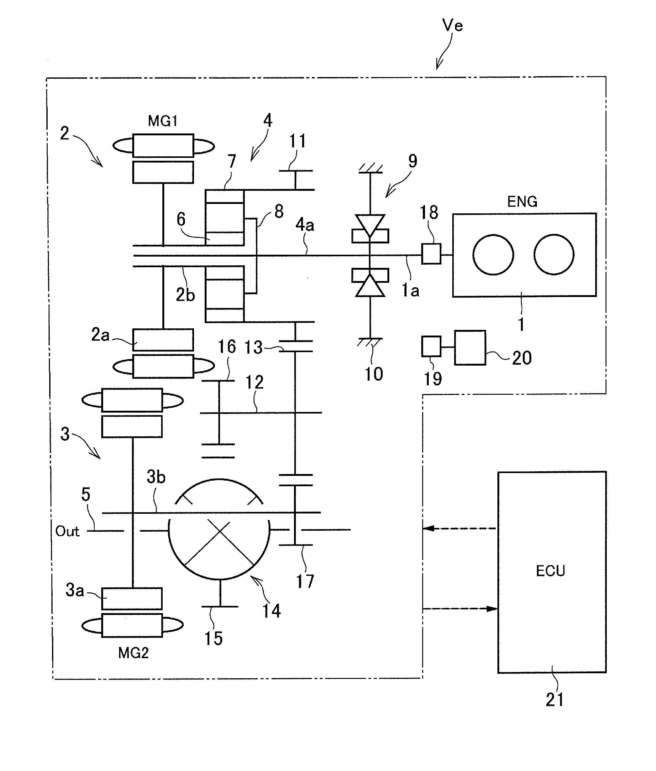
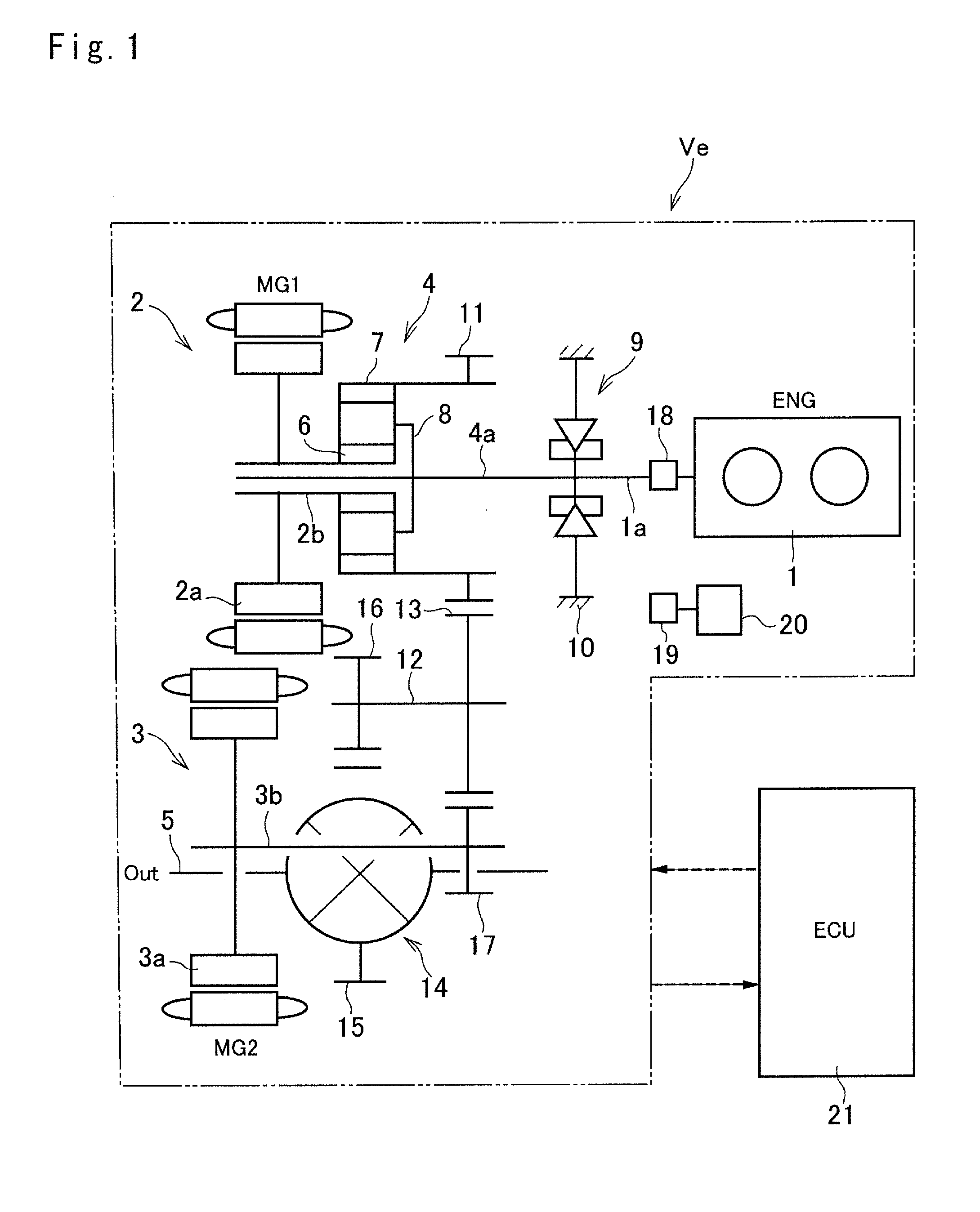
[0030]Referring now to FIG. 1, there is shown a preferred example of a structure of the electric vehicle to which the present invention is applied. A prime mover of the electric vehicle Ve is comprised of an engine 1 (ENG), a first motor-generator 2 (MG1), and a second motor-generator 3 (MG2). A power of the engine 1 is distributed to the first motor-generator 2 side and to a drive shaft 5 side through a power distribution device 4. Meanwhile, an electric power generated by the first motor-generator 2 can be supplied to the second motor-generator 3 so that the second motor-generator 3 is driven to generate a power for assisting driving force to rotate the drive shaft 5.

[0031]The engine 1 is started and stopped electrically, and output power thereof is also adjusted electrically. Specifically, given that a gasoline engine is used as the engine 1, an opening degree of a throttle valve, an amount of fuel supply, a commencement and a termination of ignition, an ignition timing etc. are ...


PUM


Abstract

A control system for electric vehicle is provided. The control system is applied to an electric vehicle (Ve) having a motor (2, 3) and an electric oil pump (19) driven by a pumping motor (20). The control system is configured to activate the electric oil pump (19) with a predetermined duty cycle when a main switch is turned on to bring the vehicle (Ve) into a ready-on state where the vehicle (Ve) is ready to travel.

Description

[0001]The present invention claims the benefit of Japanese Patent Applications No. 2014-179826 filed on Sep. 4, 2014 with the Japanese Patent Office, the disclosures of which are incorporated herein by reference in its entirety.BACKGROUND[0002]1. Field of the Invention[0003]The present invention relates to a control system for a hybrid vehicle and an electric vehicle powered by at least one motor, and especially to a control system for an electric vehicle having an electric oil pump that establishes hydraulic pressure driven by its own electric motor.[0004]2. Discussion of the Related Art[0005]JP-A-2006-161850 describes a hydraulic supply device that is applied to a hybrid vehicle having an engine and a motor as a prime mover, and configured to supply operating oil to a transmission while stopping the engine. According to the teachings of JP-A-2006-161850, the hydraulic supply device is comprised of a mechanical oil pump activated by the prime mover of the vehicle, an electric motor...

Claims


Application Information

Patent Timeline
Patent Type & Authority Applications(United States)
IPC IPC(8): F01M1/02B60L11/00
CPCB60L11/00F01M1/02F01M1/12F01M2001/123F01M2005/026B60L50/00
Inventor NISHIMINE, AKIKO
Owner TOYOTA JIDOSHA KK
Why Eureka
Eureka Blog
Learn More