High voltage tube tank for a portable x-ray

a high-voltage tube tank and portable technology, applied in the direction of x-ray tube electrodes, x-ray tube structural circuit elements, electrical apparatus, etc., can solve the problems of poor mobility and portability of conventional high-voltage tube tanks, increase in the volume and weight of high-voltage tube tanks, etc., and achieve the effect of innovatively reducing the size of the tube tank in the portable x-ray system

Inactive Publication Date: 2016-03-10
KK DIGIMED
View PDF7 Cites 6 Cited by
  • Summary
  • Abstract
  • Description
  • Claims
  • Application Information

AI Technical Summary

Problems solved by technology

The conventional high voltage tube tank has a square-shaped hexahedral structure, and in the case 1 of the parted tube tank, an x-ray tube 10, a high voltage transformer 20 and a high voltage rectification circuit 30 are built in the far distance from one another, and the remaining inner space is all filled with insulating oil L. Thus, the overall volume and weight of the high voltage tube tank increases, making it difficult to embody miniaturization and weight reduction.
That is, the conventional high voltage tube tank has faced a problem of poor mobility and portability owing to difficulties in miniaturization and weight reduction.

Method used


Image

  • High voltage tube tank for a portable x-ray
  • High voltage tube tank for a portable x-ray
  • High voltage tube tank for a portable x-ray

Examples


Embodiment Construction

[0021]Some desirable embodiments are described in detail hereinafter with reference to the figures. With regard to describing the present invention, it should be noted that the terms used to describe the components of the present invention are intended to correspond to the function performed by the respective components, and they are not intended as a limitation on the technological scope of the present inventions.

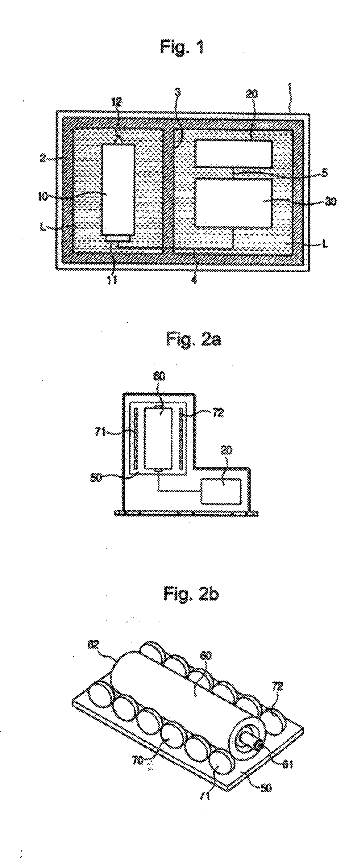
[0022]FIG. 2a is a block diagram illustrating the placement of x-ray tube in the high voltage tube tank of portable x-ray system in accordance with an embodiment of the present invention;

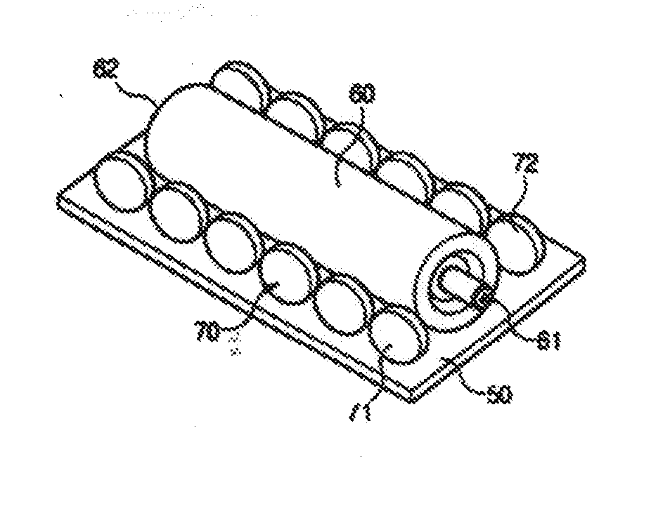
[0023]FIG. 2b is a three dimensional diagram illustrating the placement of x-ray tube in the high voltage tube tank of portable xray system in accordance with an embodiment of the present invention;

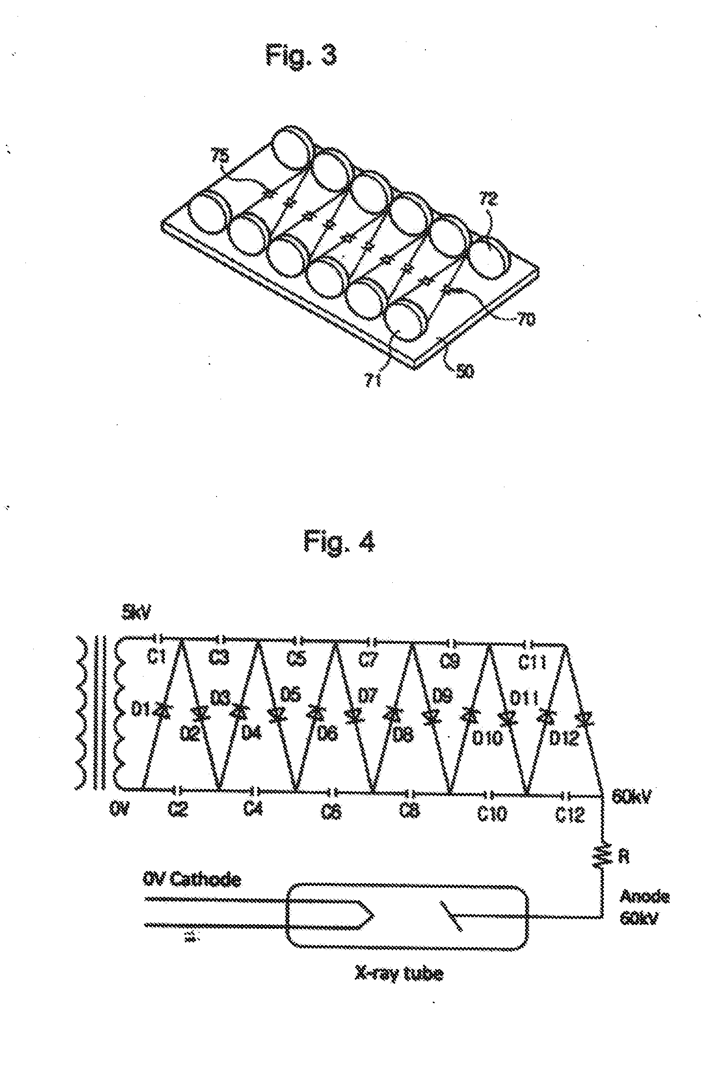
[0024]FIG. 3 is a three-dimensional diagram illustrating the high voltage circuit board in the high voltage tube tank of portable x-ray system in accordance with an embodiment of the present inv...


PUM


Abstract

The high voltage tube tank of x-ray system is embodied by miniaturizing the portable x-ray system for better mobility and portability. The high voltage tube tank of portable x-ray system comprising of an xray tube for generating x-rays, a high voltage transformer for generating high voltage, a high voltage rectification circuit for transforming and boosting AC voltage to DC voltage, and a housing for storing the apparatuses thereof, is configured in such a way that the high voltage rectification circuit is comprised of multiple high voltage capacitors linearly aligned on both sides of the circuit board and the high voltage diode built between the confronting high voltage capacitors, wherein the x-ray tube is placed between the high voltage capacitors thereof.

Description

SPECIFICATION TECHNICAL FIELD[0001]The present invention is about a high voltage tube tank of x-ray system, and in detail, it relates to the high voltage tube tank of portable x-ray system embodied by miniaturizing the portable x-ray system for better Mobility and portability.BACKGROUND OF THE INVENTION[0002]In general, the x-ray system has been frequently used for medical or industrial purposes. The xray system is comprised of an x-ray tube for generating x-rays, a high voltage transformer for generating high voltage and a high voltage rectification circuit for transforming and boosting AC voltage to DC voltage.[0003]FIG. 1 illustrates a block diagram of the existing x-ray system, and the conventional x-ray system is structured in such a way that an x-ray tube 10, a high voltage transformer 20 and a high voltage rectification circuit 30 are embedded in a high voltage tank tube.[0004]The high voltage tank tube of the conventional system requires a compact structure for realizing mob...

Claims


Application Information

Patent Timeline
Patent Type & Authority Applications(United States)
IPC IPC(8): H05G1/10H01J35/08
CPCH05G1/10H01J2235/02H01J35/08H05G1/06H01J35/025H05G1/22
Inventor KWAN, YOUNG, BAE
Owner KK DIGIMED
Why Eureka
Try Eureka