Bi-directional Boost-Buck Voltage Converter

a voltage converter and bi-directional technology, applied in the direction of power conversion systems, dc-dc conversion, instruments, etc., can solve the problem of exceeding the peak power capability of portable energy reservoirs

Inactive Publication Date: 2010-02-25
ADVANCED ANALOGIC TECHNOLOGIES INCORPORATED
View PDF13 Cites 19 Cited by
  • Summary
  • Abstract
  • Description
  • Claims
  • Application Information

AI Technical Summary

Benefits of technology

[0012]An embodiment of the present invention includes a bi-directional boost-buck voltage converter. The Boost-Buck converter provides a simple, low cost, high efficiency method to both pre-charge a high voltage, supplemental energy reservoir (a SupER) from a high capacity but low voltage battery pack, and to discharge the SupER into a load. Both pulsed cycle (as with a camera flash—one “charge” cycle, followed by a pause of relatively indeterminate length, and then one “discharge” cycle, with perhaps another pause) and continuous cycle (as with video lighting, for example—numerous cycles of “charge” and “discharge” following some orderly scheme) from the battery pack through the load are supported.
[0013]In addition to the SupER, the Boost-Buck converter also comprises an inductor, three or four switches (typically MOSFET devices but other types of devices may be used to suit the needs of differing applications) and a controller. The circuit utilizes these same energy storage and control elements during both charge and discharge periods for maximum performance, minimum cost, and minimum solution size.
[0022]The controller can receive instruction from the containing device via a number of different methods, but one embodiment would use one serial connection to implement a small set of instructions. As an example, consider the case where the controller includes an enable pin EN. Toggling EN might initiate a charge / discharge cycle of the boost capacitor using pre-programmed parameters of allowable current, voltage, etc. Holding EN low might indicate continuous mode while the pin is held low. In the case of an LED being powered from the battery via the boost capacitor, this continuous mode would serve to provide near constant illumination (as seen to the human eye) as the LED quickly cycles on and off.

Problems solved by technology

This greatly exceeds the peak power capability of portable energy reservoirs, commonly single cell Lithium-ion / polymer battery packs.
This limitation is partially due to the high series impedance of the Lithium-ion / polymer battery pack (or equivalent series resistance, ESR), which can exceed 300 mΩ for an aged battery pack.

Method used


Image

  • Bi-directional Boost-Buck Voltage Converter
  • Bi-directional Boost-Buck Voltage Converter
  • Bi-directional Boost-Buck Voltage Converter

Examples


Embodiment Construction

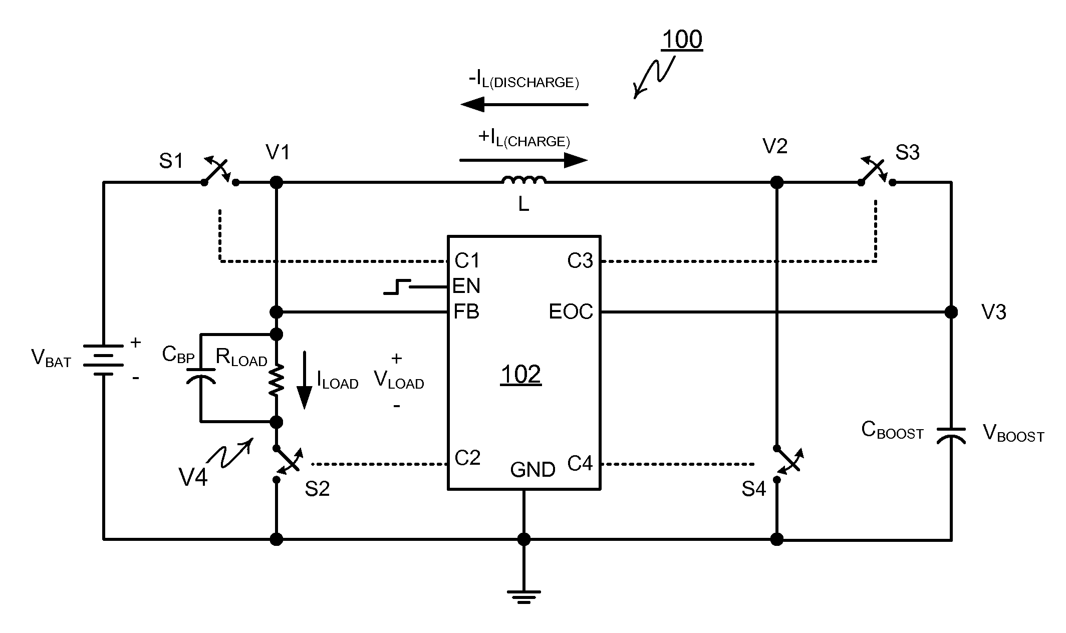
[0046]FIG. 6 shows one preferred embodiment of the present invention, generally designated 100. Converter 100 includes an integrated controller designated 102 and four MOSFET switches S1, S2, S3 and S4. Switch S1 is connected between the positive supply voltage of the battery pack and a node V1. A string of 4 FLEDs (represented in the drawing by the resistor RLOAD) is connected in parallel with the bypass capacitor between the node V1 and the switch S2. The switch S2 is connected, in turn to ground.

[0047]An inductor L is connected between the node V1 and a node V2. Switch S4 connects the node V2 to ground. The switch S3 connects the node V2 to a node V3. The boost capacitor (CBOOST) connects the node V3 to ground.

[0048]Each of the switches S1 through S4 is connected to and operated by controller 102. Controller 102 is also connected to monitor a feedback voltage VFB at node V1 and an End-Of-Charge voltage VEOC at node V3.

[0049]Converter 100 receives “commands” from its containing de...


PUM


Abstract

A bi-directional Boost-Buck voltage converter includes a controller, a high-voltage capacitor, a lower-voltage battery, a resistive load, an inductor, and three or four switches, and provides a mechanism to efficiently provide power to the resistive load from the battery. It uses two configurations of the switches to configure the battery, the inductor, and the capacitor in a boost converter configuration to charge the capacitor from the battery. It uses two different configurations of the switches to configure the capacitor, the inductor, and the resistive load in a buck converter configuration to discharge the capacitor through the inductor and the resistive load.

Description

RELATED APPLICATIONS[0001]This application is related to the subject matter of a concurrently filed application entitled “Control Method for DC / DC Converters and Switching Regulators.” The disclosure of the concurrently filed application is incorporated in this application by reference.BACKGROUND OF THE INVENTION[0002]The availability of high brightness, high efficiency, full-spectrum white light Flash LEDs (FLEDs) allows portable systems designers to consider a single, integrated replacement for other light sources (such as Xenon flash and video lamp) that are required to support digital still photography and digital video. Simplified FLEDs drive requirements allow accurate control of output light levels and lighting period, allowing optimization of output light characteristics (color gamut, color temperature, etc.). This improved control opens the door for a single FLED light source to support short bursts (camera flash) and constant illumination (video illumination).[0003]For ade...

Claims


Application Information

Patent Timeline
Patent Type & Authority Applications(United States)
IPC IPC(8): G05F1/00
CPCH02M3/1582G03B15/03
Inventor HAWLEY, STEPHEN W.
Owner ADVANCED ANALOGIC TECHNOLOGIES INCORPORATED
Why Eureka
Try Eureka