Apparatus for Multi-purpose Exercise

a multi-purpose, exercise technology, applied in sport apparatus, resistance force resistors, gymnastics, etc., can solve problems such as failure and snapping of ropes, and achieve the effects of reducing contact, minimizing stress on the line, and enduring concentrated stress

Inactive Publication Date: 2016-03-17
WAYS OF WELLNESS
View PDF2 Cites 8 Cited by
  • Summary
  • Abstract
  • Description
  • Claims
  • Application Information

AI Technical Summary

Benefits of technology

[0008]The invention is directed to a method and apparatus for coupling a tubular bar of an exercise device to a flexible line, such as an elastic rope. The present invention provides a relatively strong mechanical link between the handle and the flexible line that will effectively withstand the concentrated stress placed on the link during use of the exercise device. The newly designed retainer with the extruded cut feature allows for an improved lightweight component to be used in the coupling assembly. In addition, the present invention is configured to reduce contact between the flexible line and the handle, thereby minimizing stress on the line.
[0009]The apparatus comprises at least one rigid bar of an exercise device and an elastic flexible line having an end portion extending through a circumferential opening in the handle. The flexible line is secured within an inner lumen of the handle by a joining assembly. A joining assembly comprises a retainer positioned within an inner lumen of the handle and defining a hole for receiving the end portion of the flexible line. The retainer is designed for manufacturability of injection molding by including a 3-point curved cut out feature which also allows for a more rigid and lightweight component of the joining assembly. The coupling assembly further includes a fastener for securing the end portion of the flexible line to the retainer to thereby fix the line to the handle.
[0010]The method includes the retainer which slides into the open end of the bar. In addition, the retainer defines a lip projecting from one of its surfaces around the hole. The lip is sized to minimize contact between the flexible line extending through the hole and the bar. This reduces the surface friction between the handle and the line, thereby decreasing the wear on the line.
[0011]The fastener is preferably a conically shaped screw having a first end extending through an open end of the flexible line. The screw comprises a second end with a larger diameter than a diameter of the retainer hole for inhibiting the screw from passing through the retainer hole to thereby prevent the flexible line from being released from the retainer. Preferably, the second end comprises a protruding lip that mates against the retainer wall to prevent passage of the screw through the retainer hole. The retainer, including the new and improved extruded rectangular cut out provides optimum joining between the screw and elastic rope. This is done by embedding the joining of the tubular bar to the elastic rope in a particular housing within the retainer. The extruded cut feature is makes the retainer lightweight. The half arc protrusion added on the opposite end of the extruded cut allows for balancing of the retainer component. The screw may also include a ridge protruding from the screw and forming a spiral shape towards the first end of the screw for gripping onto an inner wall surface of the flexible line. This spiral ridge digs into the flexible line, providing a strong mechanical link there between.
[0012]The method of the present invention comprises directing an end portion of the flexible line through the circumferential opening in the handle and guiding the end portion through a hole in the retainer. The end portion is then fastened to the retainer and the retainer is positioned within the inner lumen of the handle to thereby fix the flexible line to the handle. Preferably, the end portion of the line is fastened to the retainer by inserting a first end of the conical screw through an open end of the flexible line and gripping the inner wall of the flexible line with a spiral ridge protruding from the screw. One of the advantages of this method is that the screw and the retainer can be easily replaced by engaging a lip on the screw with, e.g., a pair of pliers, withdrawing the screw from the flexible line and guiding the line back through the hole in the retainer. Features and advantages of the improved retainer will appear from the following description in which the preferred embodiment has been set forth in detail in conjunction with the accompanying drawings.

Problems solved by technology

The perpetual application and wearing of the elastic rope when coming in direct contact to the metal material of the tubular bar has caused injuries in previous designs as the tensile stresses have eventually caused the elastic rope to snap and fail.

Method used


Image

  • Apparatus for Multi-purpose Exercise
  • Apparatus for Multi-purpose Exercise
  • Apparatus for Multi-purpose Exercise

Examples


Embodiment Construction

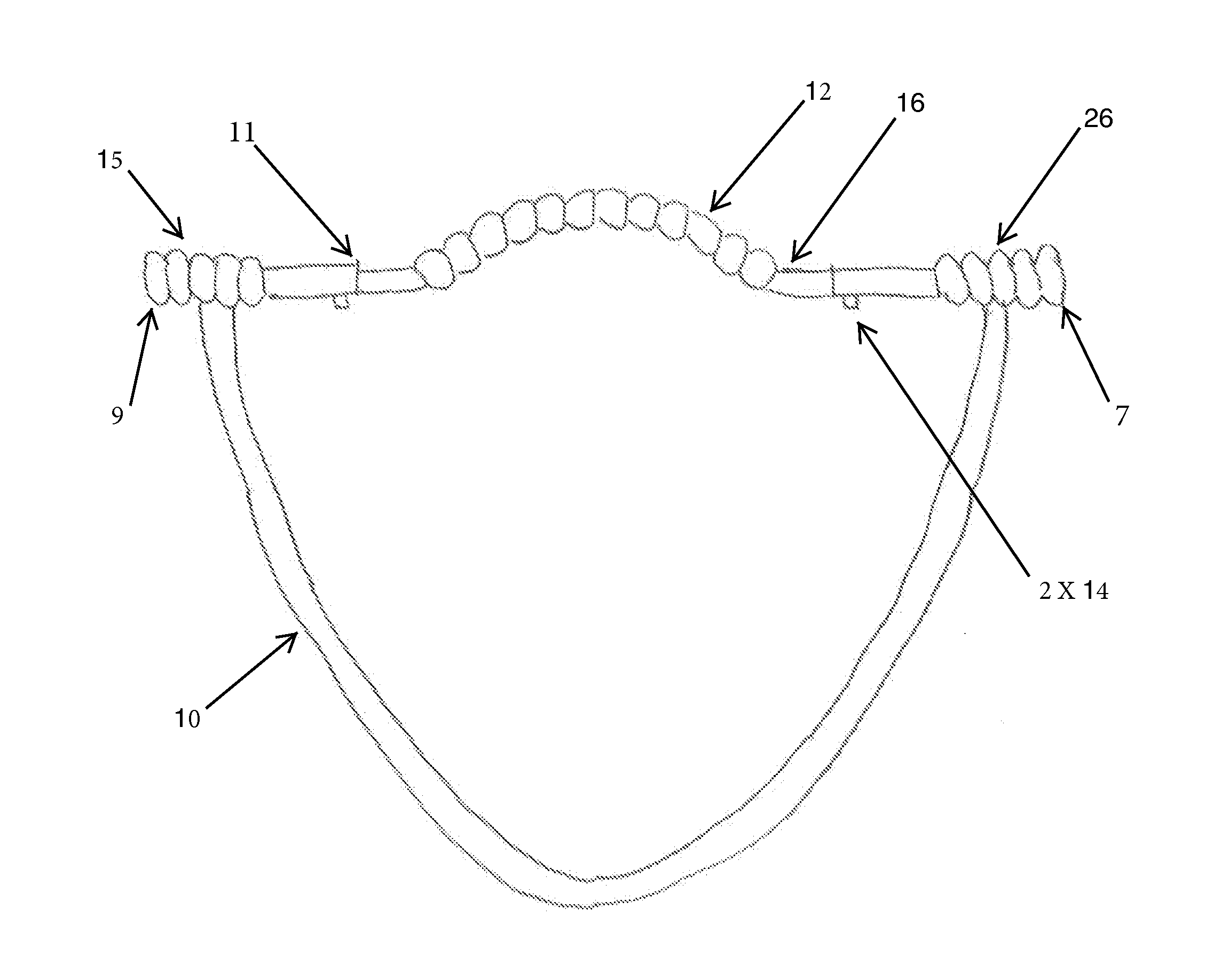
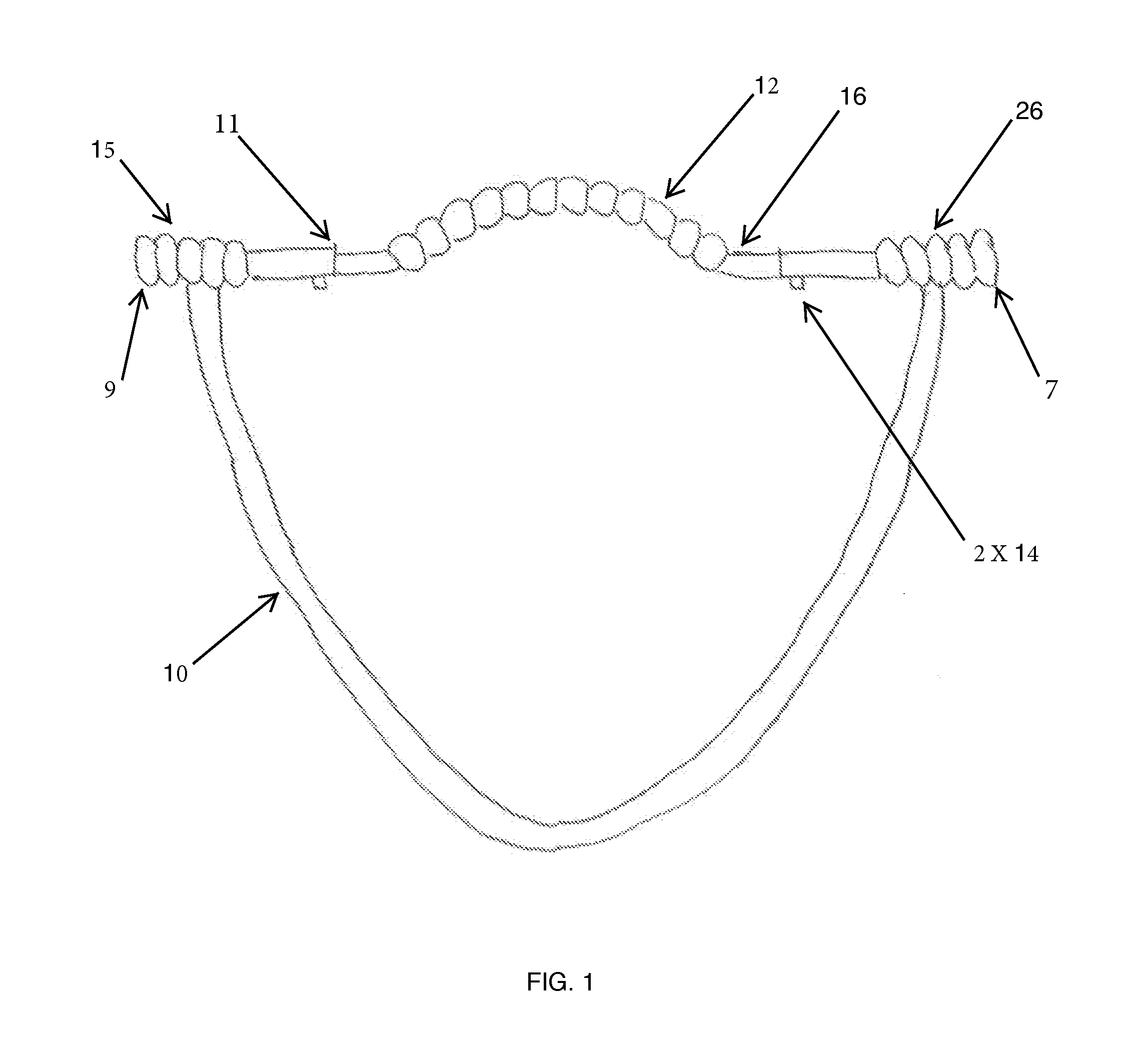
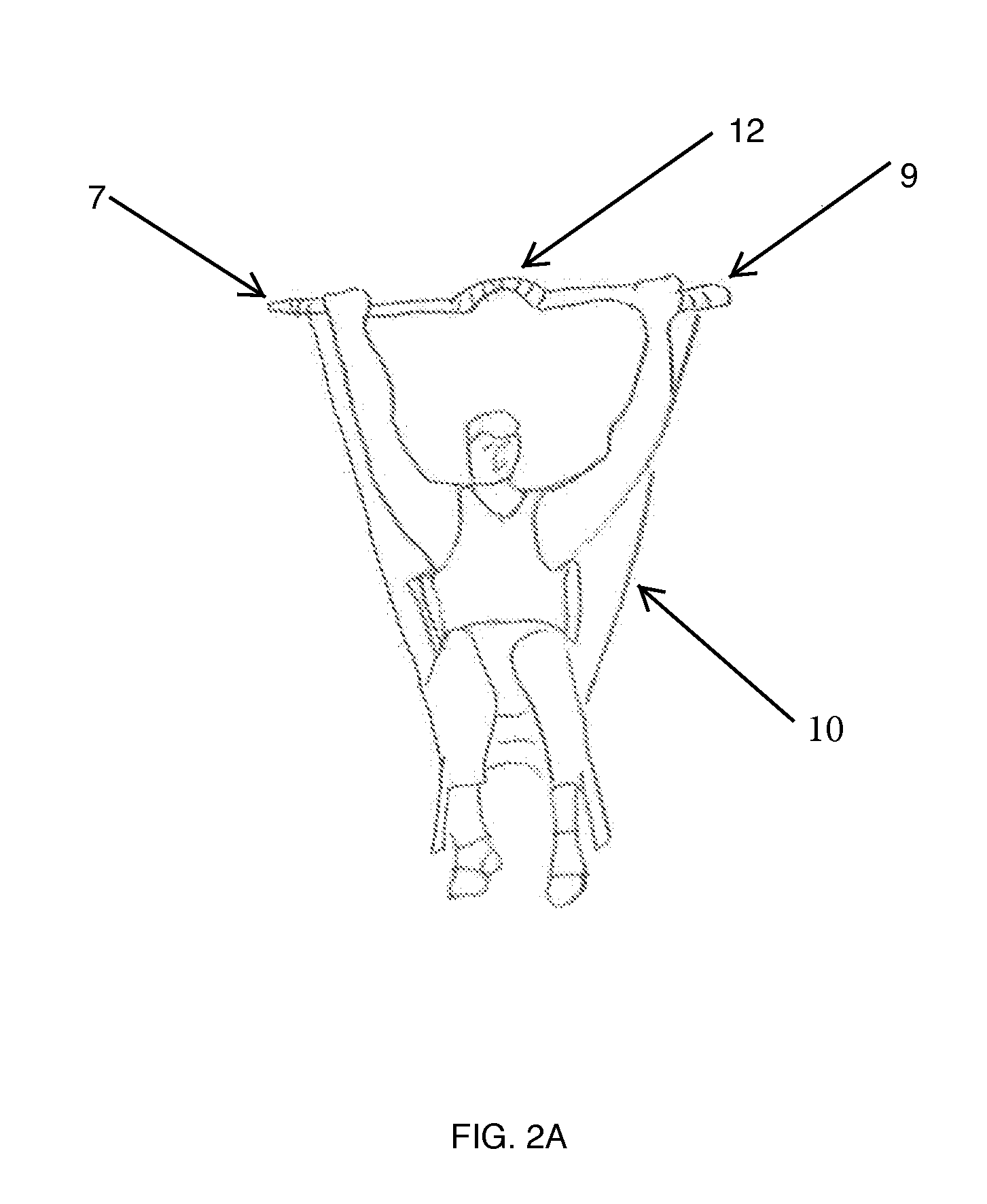
[0018]Referring to the drawings in detail, wherein like numerals indicate like elements, a multi-purpose exercise device 3 is illustrated in FIG. 6 according to the principles of the invention. Exercise device 3 generally includes a pair of rigid gripping handles 7, 9 with a center bar 11 and attached to an elastic flexible line 10.

[0019]Referring to FIGS. 6 and 8A-8C, handles 7, 9 each comprise an elongated cylindrical body 11, preferably constructed of metal, such as aluminum or stainless steel. Preferably, cylindrical bodies 11 on both ends have substantially identical diameters and lengths to facilitate use of the device when handles 7, 9 are separated from bar 13. Center bar 8 includes a release button 14 for releasably attaching handles 7, 9 to center bar 13. Release buttons 14 on both sides include compressed springs (not shown) having protrusions that extend through corresponding holes in handles 7, 9, to lock the handles to center bar 13, thereby preventing them from rotati...


PUM


Abstract

The apparatus according to this invention involves connection of a tubular bar (7, 9) with gripping features for the hands and behind the neck, to a tension resistant elastic rope for performing various aerobic exercises. The tension resistant rope is guided through to an opening in the tubular bar (60) which then joins to a newly designed retainer (30). The retainer includes a hole (40) for the elastic rope to feed through. As part of the retainer assembly, a fastener (32) is used to couple the elastic rope to the retainer. The improvement of the retainer features an extruded rectangular cut (41) allowing a lightweight and more robust mechanical linkage between the elastic rope and the tubular handle.

Description

FIELD OF THE INVENTION[0001]This invention generally relates to the technology for multi-purpose exercise. In particular, this invention relates to a new and improved joining feature of a tension resistant exercise apparatus.BACKGROUND OF THE INVENTION[0002]The invention relates to a new and improved joining feature of a tension resistant exercise apparatus. The apparatus is used for multi-purpose exercises including strengthening and conditioning of the human body. Distinctively, the invention involves the mechanism and apparatus for joining a flexible / elastic rope to a tubular metal bar in the multi-exercise device.[0003]With perpetual advancements in the field of biology and kinesiology, exercise and health continue to be at the forefront of study and growth. Over the last twenty years a prodigious amount of exercise products have been introduced to the consumer market. In today's constantly evolving technology, there are new manufacturing methods and more effective technologies ...

Claims


Application Information

Patent Timeline
Patent Type & Authority Applications(United States)
IPC IPC(8): A63B21/00A63B21/055
CPCA63B21/0557A63B21/4039A63B21/4035A63B21/0442A63B21/285A63B23/03525A63B2022/0079A63B21/169
Inventor VIAL, FREDERIC
Owner WAYS OF WELLNESS
Why Eureka
Try Eureka